


6 Q&A about compact in-die transfer tooling
New technology brings large-part transfer capabilities to small-part applications
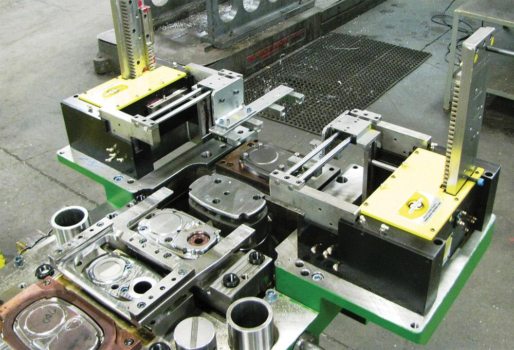
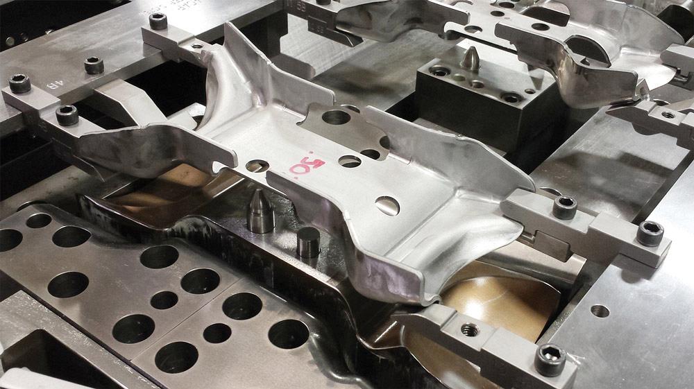
The compact in-die transfer tool mounts directly to the stamping die, becoming part of the die.
Compact in-die transfer tooling is a new and emerging technology in the metal stamping industry. Although in-die transfer systems have been around for several years, a new twist on the old technology brings together the flexibility of a press-mounted transfer system to small-press and small-part applications.
Many parts currently being stamped on progressive dies may be better suited to run on compact in-die transfer dies. A transfer process can provide the best of both worlds.
1. What Is a Compact In-die Transfer System?
It is a small transfer system that mounts directly to the stamping die, becoming part of the die (see lead image). The in-die transfer tool is set up and run in continuous mode, just like a progressive die.
The in-die system has been re-engineered to fit onto a die shoe rather than around the entire die like the original transfer die technology.
2. What Are Its Best Applications? Which Parts Are Most Suitable?
Although the compact in-die transfer system is not applicable for all parts, some circumstances make it highly suitable.
Precut Blank, Loose Part. A compact in-die transfer tool works well with precut blanks or loose parts that are fed into the tool via a blank feeder.
Ladder Carriers, Stretch Ribbons. Some part features interfere with a progressive die carrier attachment. In this case, the system is useful because, unlike progressive dies, transfer tools do not need a coil or carrier attachment point. Stretch ribbons, therefore, can be eliminated in transfer tools along with the multiple trim stations required upfront to shape the ribbons (see Figure 1).Nesting Complications. In some situations, nesting creates a poor manufacturing condition. Space may be needed between parts for cams or die steels. A compact in-die transfer can be used to expand or decrease space between stations as needed (see Figure 2).
Pinch Trim Prevention. Unlike progressive dies, a transfer tool does not have a coil or carrier attachment point to constrain the entire die process. This gives the tool engineer the freedom to break some rules of progressive die design. One of these rules is that the cutoff can happen much earlier in the process. The tool engineer is then free to trim, form, and coin the entire outside of the blank or part. This is specifically why pinch trims and the burrs associated with them can be eliminated (see Figure 3).
Line Dies. A compact in-die transfer can eliminate line dies or offline operations. Because the part is free from the coil, many line die operations can be brought back into the higher-speed transfer tool versus the slower offline operation (see Figure 4).
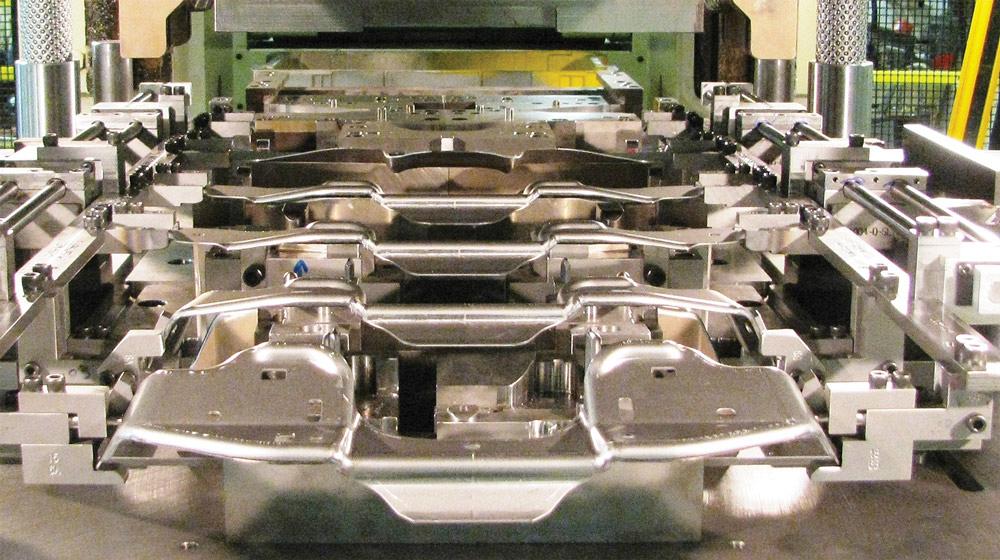
Figure 1
A compact in-die transfer eliminated three stations to trim stretch carriers.
Poor Cutoff, Die Lock. The part cutoff happens much earlier in a transfer tool process. Cutoff and forming operations then can be performed in separate, subsequent die stations, eliminating the poor cutoff and die lock conditions (see Figure 5).
Repositioning. The system is suitable when a part must be turned, rotated, or otherwise repositioned, because the part is unattached to an outside carrier (see Figure 6).
Press Utilization, Small Parts. A good in-die transfer application is a part that lends itself well to a transfer process but is too small to cost-justify running a large transfer press (see Figure 7).
Deep-drawn Parts. Unlike in a progressive die, in a transfer die, the timing of the upper and lower pad of one station is not tied to the other stations. This freedom of die timing permits upper forming punches to be mounted directly to the upper die shoe. The drawing or forming work is done directly by the ram (see Figure 8).
Costly Raw Materials, Material Savings. Stampers seeking to reduce the volume of high-priced raw material they consume may be able to save about 25 percent when they use compact in-die transfer dies compared to progressive dies. In a transfer application, the blank can be nested in the coil for the maximum material utilization and be repositioned later in the die for tooling considerations (see Figure 9).
3. How Can the System Provide Cost Savings?
Although the potential material reduction is not the only cost factor, it can reap the largest cost savings (see Stamper Avoids Getting Boxed In sidebar).
Besides the obvious cost savings realized by the size reduction over the original technology, additional savings stem from the simplification of the transfer-to-press interface. The transfer motions, part positions, and limit clutches are monitored and interfaced with the press controller, not a separate transfer system controller.
Cylinder Savings. Another opportunity for cost savings is in the reduction of nitrogen cylinders. Because the upper and lower pad timing of one station is not tied to the other stations, the upper forming punches can be directly mounted to the upper die shoe. The forming work can be done directly by the ram, and the need to synchronize each station’s pad timing with upper nitrogen cylinders is not required.
Trim Cost Savings. One other simple freedom that can save trim costs is in the free rotation of a part. In a transfer application, the part is free to reposition itself as the transfer fingers retract from a station. Tool designers can take advantage of gravity and let the part tip to improve the process. For example, the designer can let a part tip down to allow for a direct trim rather than using a cam trim. This very simple and inexpensive option can truly simplify a tool design, reducing tool costs and improving part quality in the process.
Standardization Cost Savings. The transfer components have been standardized to reduce costs. Many stamping manufacturers looking to reduce overall tooling costs and build time have designed projects around families of parts with interchangeable tooling. The transfer system also can be engineered to use on multiple presses and with different press stroke lengths.
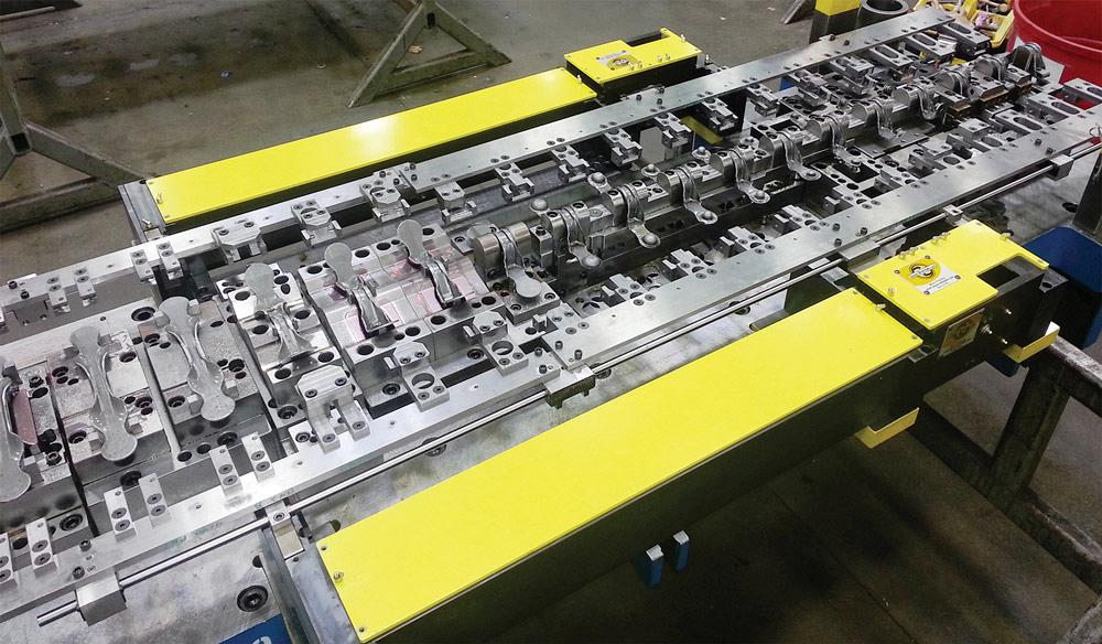
Figure 2
A compact in-die transfer allows for increasing or decreasing space between stations.
4. What Types of Tools Are Available?
Most transfer tooling is coil-fed with traditional feed equipment.
A full compact in-die transfer tool is optimal when all of the stations are set up for transfer. Many of these tools take advantage of offline blanking, and in place of a coil feed with a blanking station, a part feeder is added to the process. A hybrid compact in-die transfer tool is a balance between progressive stations and transfer stations. This style is a great option when the die process has conditions that suit both transfer and progressive styles of tooling (see sidebar).
Another common style is a partial compact in-die transfer tool. This style of die is applicable when most of the die stations are progressive and only the final die station is set up for transfers. Often, this type of tool is the best approach to eliminating sharp pinch trim burrs, forming a flange under a part, or completing a box section.
5. What Are the Basic Models?
Most systems can be obtained in both a 2- and a 3-axis model. The most common is the 3-axis, because it offers more flexibility and processing options.
Both models have a drive-in/drive-out and pitch motion. The 3-axis system provides part lift; the 2-axis does not. The 3-axis system lifts parts so that they clear the lower tooling as the system pitches forward and sets them in the next stations. The part gauges can be mounted in the lower or upper tool, whichever best suits the part or die conditions.In a 2-axis transfer, the system slides the parts across die steels between die stations. The part locators or gauges are mounted in the upper die, and the gauges must position the parts for the work to be done as the die closes.
6. How Is It Suitable for Bench Cycling, and Why Is That Important?
One feature of this system that can improve tool development is its ability to be cycled on the bench. The motions of the transfer system can be manually manipulated to simulate the working transfer.
Being able to manually operate it without installing it on an actual press can reduce press tryout time. The transfer finger final fit-up can be done in a less costly toolroom environment rather than in the pressroom, which takes up valuable production resources. Bench cycling also makes the tool more accessible for troubleshooting.
Remember Abraham Maslow’s hammer law: “…it is tempting, if the only tool you have is a hammer, to treat everything as if it were a nail.” A compact in-die transfer system can be a new tool in sheet metal stampers’ toolboxes.
Jacar Systems LLC, bgunst@jacar-systems.com, (586) 321-1401, 10321, Arnold Rd. Fair Haven MI.
Industrial Stamping and Manufacturing, 16590 Thirteen Mile Road, Roseville, MI 48066, 586-772-8430, atomlan@industrialstamping.com, www.industrialstamping.com
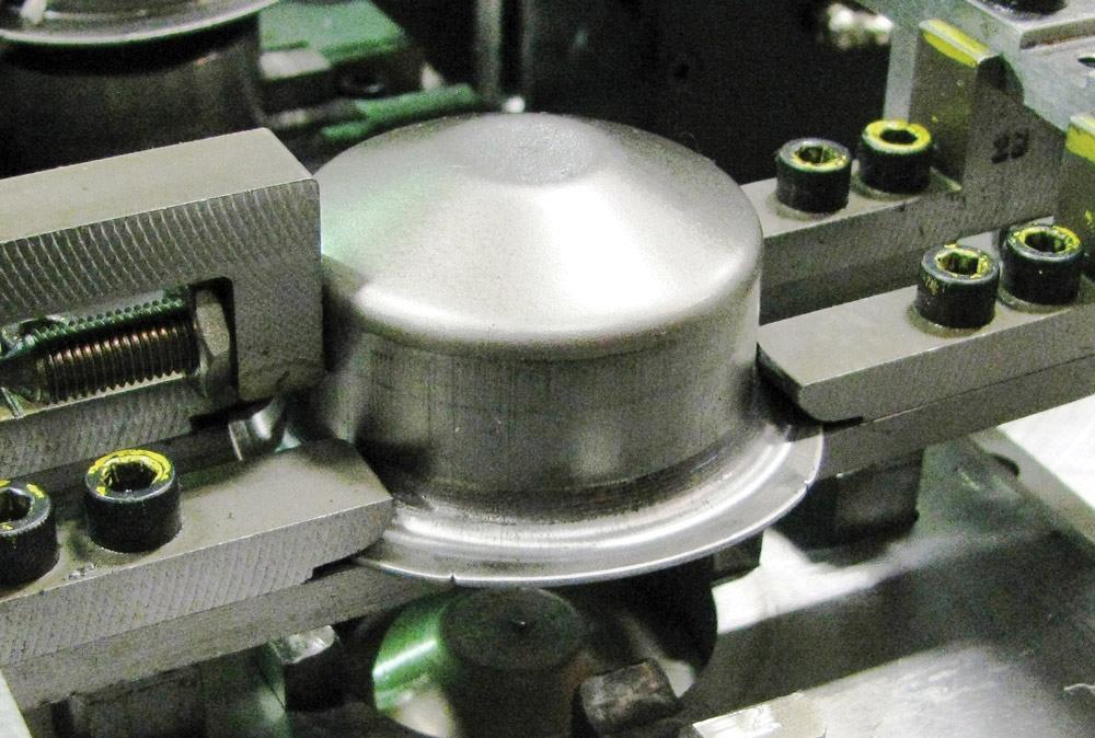
Figure 3
Because the cutoff can occur earlier in the process, the system can eliminate pinch trim and burrs.
Stamper Avoids Getting Boxed In
Industrial Stamping & Manufacturing is a 60-year-old family-owned business. The ISO 9001:2008-certified manufacturer, located in Roseville, Mich., has 40 employees. The company processes steel coils 30 inches wide and about 0.2 in. thick on presses of speeds up to 100 strokes per minute. Its largest press is 400 tons with a 108-in.-wide bed.
The manufacturer recently realized cost savings, process improvements, and increased flexibility using Jacar’s Micro Transfer™ system for specific tooling applications.
One project involved a bracket that Industrial Stamping was considering running as a full progressive die. The stamper used Jacar’s compact in-die transfer system and realized an annual material reduction of 66,000 pounds, three fewer die stations, and a 16-in. shorter die as a result. Industrial Stamping was able to pass along a $20,000-a-year cost savings to its customer.
Bolstered by that success, Industrial Stamping used a compact in-die transfer system to draw a part with a print requirement for no burrs or sharp edges. Using the transfer system, the company removed the outside carrier, thereby eliminating the pinch trim burr. In addition, cost savings were obtained from the reduced material usage and because the manufacturer could downsize the nitrogen cylinders used to draw the part.
When the stamper faced a project with difficult forming conditions—a box-shape bracket with multiple, complex features—it explored ways to stamp it with a compact in-die transfer system.
Opinions varied as to how to best process the part to satisfy the challenging forming demands. The company decided to employ the system with a rollover device to gain the advantages of both the progressive and transfer dies. The bracket forming started in the progressive die up to where it needed to take on the box shape, and then the transfer die finished the box section. The rollover was located at the first transfer station and reoriented the part 180 degrees to allow the box sides to be formed down.
The result was a fully automatic tool that could run continuously and eliminate an offline die station. Industrial Stamping & Manufacturing General Manager Adam Tomlan said, “The Jacar Micro Transfer System has proven significant advantages which we can offer our customers. Often it is the most competitive option and puts Industrial Stamping in a good position to earn the business.”About the Author
About the Publication

subscribe now

The Fabricator is North America's leading magazine for the metal forming and fabricating industry. The magazine delivers the news, technical articles, and case histories that enable fabricators to do their jobs more efficiently. The Fabricator has served the industry since 1970.
start your free subscription- Stay connected from anywhere

Easily access valuable industry resources now with full access to the digital edition of The Fabricator.

Easily access valuable industry resources now with full access to the digital edition of The Welder.

Easily access valuable industry resources now with full access to the digital edition of The Tube and Pipe Journal.

Easily access valuable industry resources now with full access to the digital edition of The Fabricator en Español.
- Podcasting

In this episode of The Fabricator Podcast, Caleb Chamberlain, co-founder and CEO of OSH Cut, discusses his company’s...
- Trending Articles
1
Capturing, recording equipment inspection data for FMEA

2
Tips for creating sheet metal tubes with perforations

3
Are two heads better than one in fiber laser cutting?

4
Supporting the metal fabricating industry through FMA

5
Omco Solar opens second Alabama manufacturing facility
