


President
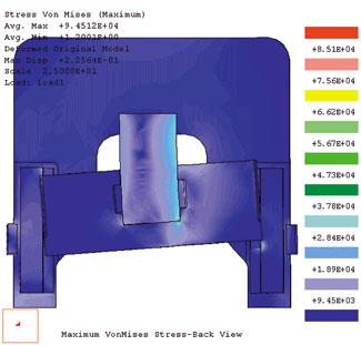 |
| Figure 1: FEA software produces graphical illustrations of the results of standard stress analysis on every side of a part. |
Your marketing department has just come up with a new product idea that requires you, the press and tooling manager, to find a new tool and perhaps a new press to make the part. The trouble is that the information about the tonnage requirement and the process is sketchy and vague. You need more information about how the part will form and the loads it will impart into the press and tooling.
By using linear or nonlinear finite element analysis (FEA), you can find the information you need to make an informed decision.
With FEA, a fabricator uses a computer-aided design system to develop a model of the part. The computer then divides the part into many small parts. The FEA software then applies standard stress analysis equations to each side of every part. After this process is complete, you can view and interpret graphical illustrations (see Figure 1) of the results.
Before you can apply this technology to presses and dies, you first must examine the actions and resulting loads that occur in a metal forming process, such as blanking, draw, and cushion forces, and the combination of these in a progressive or transfer tool.
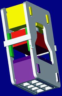 |
| Figure 2: This 3-D assembly was made on a 2,000-ton press. |
In a blanking operation, the load is a function of the material's thickness and strength, the circumference if the hole is round, or sum of the outside dimensions if the hole is not round, and the percentage of shear built into the punch.
Tonnage = (3.14 x D x S x T) / 2,000
where:
D = circumference of the hole (or sum of the outside dimensions if the hole is not round)
S = shear strength of the material in lbs./in.2
T = thickness of the steel in inches
The last operation, dividing the total by 2,000, converts the force from pounds to tons.
The load builds as potential energy in the frame of a mechanical press, as well as in the frame and hydraulic system of a hydraulic press. The sudden transformation of potential energy into kinetic energy — which occurs when the punch contacts the material and releases as the punch breaks through the material — impacts greatly on the connections between the slide and the driving mechanism. A portion of this energy also can be absorbed in the tool.
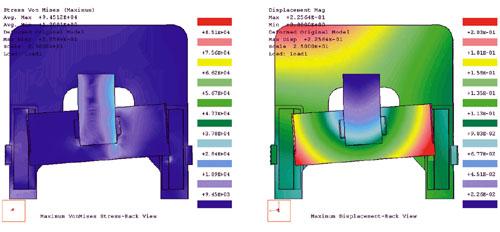 |
| Figure 3: These stress and deflection results reflect a load located off-center of the press. |
In draw forming, material thickness and strength again play a major part in creating the load. The part's shape, the radii's sharpness, and the ratio of the outside diameter to the draw depth also influence the forces developed. The equations can take many forms, depending on the shape of the part. A good reference is the Tool and Manufacturing Engineers Handbook, Vol. II — Forming (Dearborn, Mich.: Society of Manufacturing Engineers, 1984).
The forces resulting from this process are less dramatic than in blanking, but they last longer because draw forming involves stretching the material over time.
Other factors entering into this process are press speed, draw ring radii, and the amount of opposing force required on the rim of the material to eliminate wrinkling as the material is drawn into the hole.
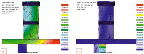 |
| Figure 4: The off-center load causing these stresses and deflections on the piston could be a blanking or forming operation. |
After you determine this load data, you can perform FEA. You should select the proper FEA software package on the basis of the software's ability to perform nonlinear, large deflection manipulations. Not all FEA software packages are capable of handling those results. Figure 2 shows a 3-D assembly made on a 2,000-ton press. It illustrates how symmetry is used to create a partial model that reflects the loads, but allows the FEA process to use a smaller model to lessen the process time. In this figure, the load is located off-center of the press.
To understand this better, refer to Figure 1, which shows the entire press. The load is placed in the press, centered in the front-to-back direction. This allows the modeler to cut the press in half, as shown in Figure 2, using symmetry to analyze the model while keeping the model as small as possible. This lessens the analysis time and prevents errors from creeping into the interpretations of the results.
Figure 3a and Figure 3b depict the stresses and deflections resulting from a load located off-center of the press. The magnitude of the deflections shown in the illustrations is greatly exaggerated to give a better picture of the movement.
Figure 4a and Figure 4b show the stresses and deflections on the piston. The off-center load could be a blanking or forming operation. You could place multiple loads in the model to represent a progressive tool.
These images are from a static, linear FEA analysis. Using the information developed from the analysis, the company making this part changed the press design to meet fatigue criteria and slide-to-bed parallelism.
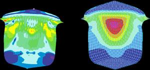 |
| Figure 5: These stress and strain results occurred in one quarter of a shell model. |
Figure 5a and Figure 5b depict nonlinear FEA analysis of the stress and strain in one quarter of the shell of a drawn part. With this type of dynamic study, you can determine, for instance, what happens to the drawn part if the press speed is changed, or what happens if the draw ring radius is changed.
From these results you could determine the shell's wall thickness, areas that may have become strained beyond an acceptable limit and may have poor surface quality as a result, or areas that are overstressed and may rupture as the process is working.
Some FEA packages can animate the results. Live pictures enhance the results and give a clearer understanding. The bottom line is that you can use a computer as a prototype tool to play what-if games before spending capital funds on the real thing.
This article is adapted from Gerry Nord's and Kevin J. Coughlin's conference presentation at FABTECH® International, Nov. 11-14, 2001, Chicago, Ill., copyright 2001 by the Fabricators & Manufacturers Association, Intl. (FMA), and the Society of Manufacturing Engineers (SME).


The Fabricator is North America's leading magazine for the metal forming and fabricating industry. The magazine delivers the news, technical articles, and case histories that enable fabricators to do their jobs more efficiently. The Fabricator has served the industry since 1970.
start your free subscription
Easily access valuable industry resources now with full access to the digital edition of The Fabricator.

Easily access valuable industry resources now with full access to the digital edition of The Welder.

Easily access valuable industry resources now with full access to the digital edition of The Tube and Pipe Journal.

Easily access valuable industry resources now with full access to the digital edition of The Fabricator en Español.
In this episode of The Fabricator Podcast, Caleb Chamberlain, co-founder and CEO of OSH Cut, discusses his company’s...


