


Provides Technical Sales and Support

A complex stamped component begins its journey as a part print. Then a CAD layout drawing marks the progression; a 3-D model, this one done in SolidWorks®, fleshes out the form and indicates any possible interference; and the die is put through a test run and the first part is produced.
Editor’s Note: Stamping manufacturer DACO Precision-Tool shares its expertise on designing and building stamping dies and forming production, based on its 31 years of experience. DACO Precision-Tool is a member of the Tool, Die & Machining Association of Wisconsin (TDMAW). DACO Precision-Tool President Randy Weber is the TDMAW’s current president.
There are many things to consider when designing a progressive stamping die for a complex part before it materializes as a fully formed, functional component. It all starts with a customer print that includes dimensions, tolerances, critical features, material, and other special requirements. Here, step-by-step, is how to take a part print for a complex progressive stamping from quote to a finished part.
After a customer order is received, it’s best to confirm your quoted price and verify that a progressive tool is truly a proper fit before beginning to design the tool. Start by determining the stock strip width and material thickness that are required, as well as what your progression length (feed length) will be based on the part size and configuration. That way, you can factor these three measurements in when you submit your initial quote. It’s important to know the stock strip and progression at the quoting stage to
calculate how much material will be required so you can provide an accurate quote (see Figure 1).
A solid modeling CAD software program is essential for you to create tooling designs and simulations (see Figure 2).
Typically, simulations are performed only for progressive tooling. Simulations add a great deal of value to complex part and tool designs. They allow you to see how everything will work in a simulated production run before you order materials and commit to a specific tool design.
Next, determine the number of stations that will be required. In general, each station is responsible for an operation.
However, in some cases when the part is very complex, it’s best to design in one or two blind stations if you need to add or change something later. When the part has many critical features, it does not always stamp out dimensionally correct during the sample run. In this situation, you may be forced to make modifications to the tool. The modifications can be difficult and very costly if you have not included blind stations in the initial tool design.
You also need to figure out how you are going to transport the strip through the tool. It’s advisable to align the strip after each progression. The pilots are designed either to align with holes in the actual part or side holes located in the carrying portion of the stock strip, which is trimmed off in the last station.
Clearance is also a significant consideration in the design phase. It has a direct correlation to the part’s material requirements. Generally, the thinner the material, the tighter the clearance needs to be. The same goes for tolerances; if a very specific tolerance range is required, the clearance must be precise—within a few thousandths of an inch.
The size of the tool and thickness of steel plates used to build the tool are based on the size, thickness, type of material, and estimated tonnage requirement for the specific part. Large, thick, hard, and high-tonnage parts require a large die. The opposite is true for small and thin parts. This leads into which press size, in terms of tonnage, bed size, stroke, and shut height, is needed for production. All tools are designed and built to a specific feed height to match the press. The feeder height should always match the height at which the stock strip enters the die.
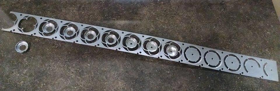
Figure 1
It’s important to know the stock strip size and progression length required to make the part to calculate how much material will be needed for quoting purposes.
Once you know which press you will use, you can now incorporate scrap removal into the tool design (see Figure 3). Each press is set up with a unique scrap removal system that must be compatible with the tool.
Finally, look at die protection. All of your progressive tools should be designed and built with short-feed and other die protection sensors. These sensors protect the tooling and are intended to stop the press when the strip isn’t located correctly or fed to the correct position to prevent die crashing or miss-hitting. Often a simple short-feed sensor is all that’s required, although eight or more different die protection sensors can be used and programmed if needed.
One tip you may want to try is to install bottoming blocks on every progressive die you build. The die bottoms out on the block instead of on the actual forming tool inserts. These setup and
bottoming blocks help the setup person get close to the required shut height and depth at which the tool needs to run. The blocks also help to prevent possible damage during setup caused by the ram being set too deep. For critical parts, as little as 0.001-in. variance in the ram height can make the difference between having a good part or bad part and a smashed tool.
Once all these factors are taken into consideration and incorporated into the tooling design, complete your 3-D CAD model. Then use the simulation feature to ensure that the tool is going to run effectively, efficiently, and precisely.
If the tool is going to be run internally, it is time to start ordering die materials. It’s a good idea to review your final design before proceeding any further. This presents an opportunity to make any necessary changes and to verify that everything will match up with the press intended for the production.
Begin by ordering the die set, tool steel, punch holders, punches, pilots, dowel pins, shoulder bolts, cap screws, nitrogen cylinders (if required), material for parallels, coil stock for the initial sample run, and any other specialized items required for the tool. You can continue working on the internal design diagram and shop prints for each specific component and section of the tool while waiting for materials to arrive. Once the materials are delivered, use the shop prints to verify each one and continue building each component and tool section per the design diagram.
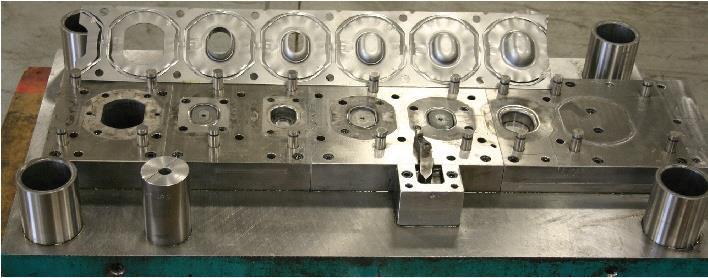
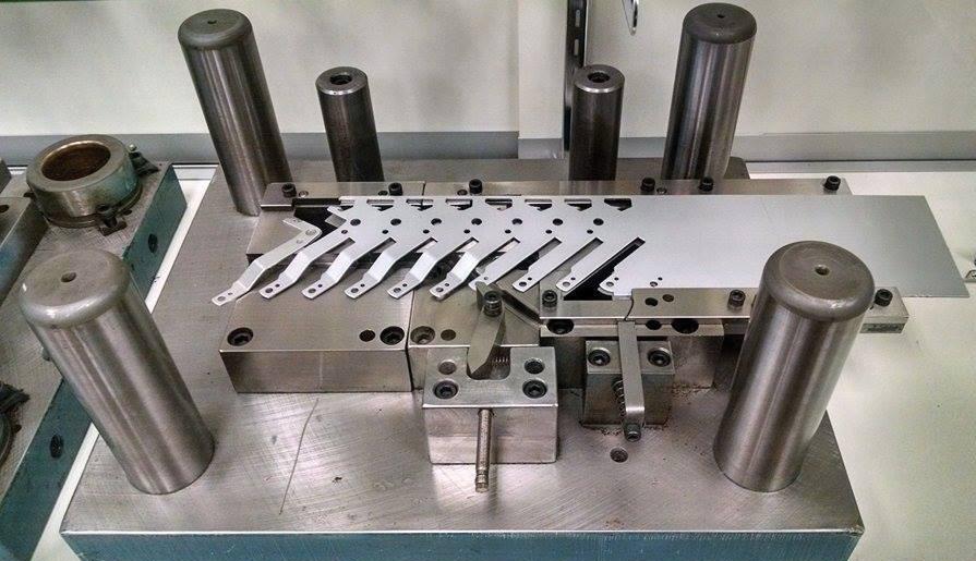
A fair amount of machining, wire electrical discharge machining, heat treating, and grinding work is required to build the die. Once the different components and sections of the tool are complete, begin final die assembly (see Figure 4). As everything comes together on the bench, check the clearance in all stations, test all moving components, and check the timing of the tool.
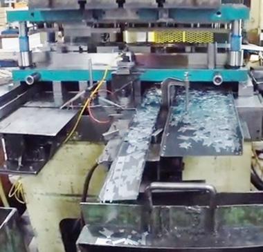
You’re almost cleared for takeoff, but before you start down the runway, first test the newly built progressive tools for troubleshooting and potential problems in a test run (see Figure 5). Look at how the die sensors are operating, press speed, how the strip moves through each tool operation, scrap removal, and how the part is ejected.
The sample run setup starts with loading the proper coil onto the uncoiler and bringing it through the straightener to take the coil set out of the material. Then take the flattened strip to the servo feeder. Next, slide the die into the press bed, align it, and clamp it in on both the top and bottom.
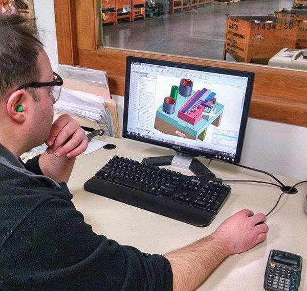
Figure 2
It’s best to do solid modeling before you order materials and commit to a specific tool design.
Another trick you can use to take the guesswork out of die setup is to add alignment blocks to your dies and press. The blocks on the press bed sit in grooves specifically machined for the sole purpose of aligning the tool. Then simply push the die back until the alignment blocks on the tool rest up against the alignment blocks on the press bed. Doing this ensures that the tool is in the bottom dead center of the press and aligned with the feeder. This will help to eliminate binding or feeding issues that may occur with a tool that is not properly aligned. This is especially critical for large progressive dies with numerous stations.
After the tool is clamped, set the tool depth. The set-up bottoming blocks are designed with a predetermined clearance, which gives you a starting point to set the initial depth. Bring the press to the bottom of the stroke and lower the shut height until the clearance between the block and the tool’s top plate matches the predetermined amount.
It is then time to feed the stock strip into the die and to cycle the press through each progression. Once you bring the strip all the way through each station of the tool, you can inspect the finished part being trimmed off at the end.
At this point, fine-tune the shut height based on the dimensions of the part being test-run. Sometimes you may hit it right on the head and don’t need to make any adjustments. Other times you’ll need to back up the ram or bring it down to yield a part with the required dimensions.
Once the depth is set and verified, program the tool with a press automation control system. A control program adds a great deal of value, accuracy, and efficiency to stamping production runs. It is a critical element for successfully producing complex stamped parts that require progressive tooling.
Start by programming the feed length (progression), feeder speed, batch count, and order count. Next, choose which sensors are to be used. Minimally, short-feed sensors should always be used on progressive tools, but other sensors that monitor part ejection, scrap ejection, high loop, and other actions can be added. Then program the cam settings that correlate with the 360-degree stroke revolution of the stamping press.
You’ll need to program when to feed; when the servo feeder opens up for the pilots to align; when to apply lubricant; when to blow air for part ejection, if required; when to engage the scrap handling equipment; and the sensors’ timing overall. After everything is programmed, this is all done automatically in one press stroke. After the initial run, the tool is saved in the program database so the parameters will be set for future production runs.
The last thing to do once everything is programmed is to set the limits of your tonnage monitor. Have it recalculate after the press is running in automatic mode so you can monitor it appropriately. Once the tonnage parameters are set, the press will stop automatically if the monitor detects tonnage below or above the set limits (usually set within 10 percent or less of the overall tonnage).
It is optimal to inspect the production run and press hourly, at minimum, to verify that the parts are being stamped consistently per the print. Once the press is running in automatic mode, these quality inspections, and coil loading, should be the only labor required.
Always double-check each stage of building a complex progressive tool before your production takes flight–there is no room for error. However, it is not uncommon to make adjustments to the tool and tweak it after or during the initial sample run. In some cases, the die may need to come in and out of the press as many as two or three times to make the appropriate changes to ensure that the tool will run at the highest level of quality and consistency.


The Fabricator is North America's leading magazine for the metal forming and fabricating industry. The magazine delivers the news, technical articles, and case histories that enable fabricators to do their jobs more efficiently. The Fabricator has served the industry since 1970.
start your free subscription
Easily access valuable industry resources now with full access to the digital edition of The Fabricator.

Easily access valuable industry resources now with full access to the digital edition of The Welder.

Easily access valuable industry resources now with full access to the digital edition of The Tube and Pipe Journal.

Easily access valuable industry resources now with full access to the digital edition of The Fabricator en Español.
In this episode of The Fabricator Podcast, Caleb Chamberlain, co-founder and CEO of OSH Cut, discusses his company’s...


