


Contributing Writer
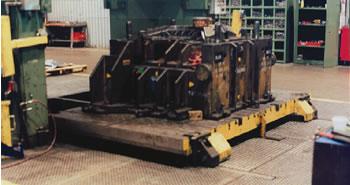 |
| Shown out of the press, the guided wheels on this 120,000-pound rigid chain rolling bolster are evident on the front face of the bolster. |
One element of changing dies in stamping presses quickly and efficiently is the use of a rolling bolster. With this equipment, the operator rolls the bolster out of the press, unbolts it from the bolster, removes it with a crane, sets the new die on the bolster and bolts it, and rolls the new bolster into the press–all within 10 to 15 minutes.
Another rolling bolster can be added at the side of the press to hold the prestaged new die. In this case, bolster 1 rolls out of the press with the old die and moves sideways to allow bolster 2 to replace it in the press with the new die. With this method, the crane becomes unnecessary, and die change time can be reduced to five minutes or less. With the use of hydraulic clamps for the bolster and die, this system can be made to run in full automatic mode, further reducing changeover time and eliminating errors caused by manual handling.
Most rolling bolster systems are purchased with new presses, typically when a new production program is started. In the past rolling bolsters have had limitations such as cost that made them unsuitable for many shops. However, new developments have helped reduce these limitations to make them suitable for more companies.
Press Bed Height. Some rolling bolster retrofits that were available in the past required a new bolster at least 12 in. thick to incorporate the mechanism. If the existing bolster was 8 in. thick, this translated into a press shut height loss of 4 in., which was undesirable in most cases, because it limited by 4 in. the size of the dies that could go into the press. It is now possible for rollout bolsters to be as thin as 5 in.
Cost. Rolling bolster systems used to be installed only in presses larger than 800 tons because cost was prohibitive when compared to the cost of the press itself. A typical contract stamper could not afford the expense. Today some competitive aftermarket systems are available for use as retrofits on small and large presses alike, if the press meets certain conditions.
• A rigid chain rolling bolster system can be installed on any straight-side press with a bed height from 0 to 30 in. off the floor. It is especially useful for bed heights from 0 to 16 in. because other means of quick die change, such as a die cart, are not suitable.
• A crane must be available above or next to the press, and the crane hook must be able to access the die from overhead.
• The bolster must be at least 5 in. thick.
• Floor space must be available or made available for the rolled-out bolster.
• The floor must be able to safely carry the weight of the die and bolster. If there is a pit, the pit steel structure may need to be reinforced.
The five main components of a rigid chain rolling bolster (see Figure 1) are:
 |
1. Lifting mechanism. The bolster must be lifted off the bed to allow rolling. One lifting method is to use a set of off-the-shelf hydraulic die lifting rollers bolted to the far edge of the bed. The bolster is notched at each end, allowing the lifter frames to lodge inside. The other method is to use hydraulic cylinders at each corner of the bolster, which lift the bolster wheels off the bed. This method usually is more expensive.
2. Wheels and rails. Four wheels and two grooved rails are mounted flush with the floor. The two front wheels fit into a groove machined on each rail for guiding purposes. The back wheels are flat and roll on top of the bed. Sometimes, when the bolster needs to roll out farther than the edge of the bed, an additional pair of wheels is added on the bed for support.
3. Rigid chain transfer mechanism. This mechanism pushes the bolster out and pulls it back in. It can be mounted on either side of the bolster, depending on space. It comprises a rigid chain system, a gearmotor, and a set of positioning switches.
4. Positioning system. In this system, two large (4-in.) cam followers are installed at the back of the press bed. A V-notch and flat notch are machined at the rear bottom of the bolster. When the bolster is pulled back into the press, the push/pull system firmly pushes the bolster against the cam followers, precisely positioning the bolster in the X and Y axes.
5. Electrical controls. Electrical controls typically comprise a main control panel with a variable-frequency drive (VFD) and a hand-held operator pendant or a console. The main panel is mounted at or near the press and houses three-phase power with a fused disconnect switch. The VFD allows the system to operate at variable and programmable speeds for acceleration, deceleration, and creep. It also provides overload safety to reduce shock loads and increase the life of mechanical components. The system's hand-held pendant gives the operator full mobility and visibility during the bolster movement. The electrical controls of a rigid chain rolling bolster are interfaced with the press controls to ensure safe operation.
A rigid chain rolling bolster system can be installed on any straight-side press with a bed height from 0 to 30 in. off the floor. It is especially useful for bed heights from 0 to 16 in., for which die carts and die transfer tables might not be suitable.
A crane must be available above or next to the press, and the crane hook must be able to access the die from overhead. The bolster must be at least 5 in. thick, and enough floor space is required for the rolled-out bolster. The floor must be able to carry the weight of the die and bolster safely. If there is a pit, the pit steel structure may need to be reinforced.
Installation usually takes one to two weeks, depending on how much pit work is required. To minimize installation time, the bolster is removed and machined to print before installation begins, allowing it to accept bolt-on components. Additional work, such as pit reinforcement, also should be done ahead of time. All components needed for the rolling bolster system should be on-site, and the press must be made available for the installation.
The most time-consuming operation is the rail installation. The rails must be leveled to within 1/16 in., and they must be held parallel to each other and the press centerline. Once the rails are leveled, they must be secured in place but not permanently set until the rolling bolster system has been tested for smooth, trouble-free operation.
The next item to install is the lifting mechanism. This can be simplified with the use of off-the-shelf lift rollers. They require eight tapped holes on the bed. Lifters need to be steel-piped to a small air-over-oil hydraulic unit mounted to an accessible part of the press for routine maintenance. The hydraulics require shop air to operate.
Other items, such as the wheels and the push/pull, should install with quick, bolt-on operations. Once the system is tried and proven, the wheels are doweled to finalize their location. Electrical control installation involves mechanically installing the main control panel, power drop, and wiring one motor and positioning cam switch.
Once the system is installed and tested with the heaviest die, and the operation of the rolling bolster is satisfactory, the rails must be set in place with high-strength epoxy grout.
Operating the rigid chain rolling bolster system is relatively easy. When the press is put in inch mode or setup mode, the rolling bolster controls are powered up to allow operation.
After the die is unbolted and the ram is raised to its top position, the rolling bolster system is activated. The bolster is raised off the bed, then pushed out of the press by the rigid chain push/pull mechanism. A crane removes the old die and installs the new die. The bolster is rolled back in against the stops to ensure accurate positioning, lowered onto the bed, and bolted. Mission accomplished.
Said Lounis is president of Serapid, 5400 18 Mile Road, Sterling Heights, MI 48314, 586-274-0774, fax 586-274-0775, slounis@serapid.com, www.serapid.com.


The Fabricator is North America's leading magazine for the metal forming and fabricating industry. The magazine delivers the news, technical articles, and case histories that enable fabricators to do their jobs more efficiently. The Fabricator has served the industry since 1970.
start your free subscription
Easily access valuable industry resources now with full access to the digital edition of The Fabricator.

Easily access valuable industry resources now with full access to the digital edition of The Welder.

Easily access valuable industry resources now with full access to the digital edition of The Tube and Pipe Journal.

Easily access valuable industry resources now with full access to the digital edition of The Fabricator en Español.
In this episode of The Fabricator Podcast, Caleb Chamberlain, co-founder and CEO of OSH Cut, discusses his company’s...


