


Marketing Manager
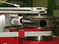
Figure 1: Tube bending simulation software ensures that a bending job can be done on a particular machine and that the bend is collision-free.
Can I bend this tube geometry on my machine? This is the most important question that you have to ask yourself before embarking on a new tube bending job (see Figure 1). The answer will determine whether the tube can be manufactured as planned.
In many instances, you answer the question only after trying the part out, tying up the machine when it could be producing parts, and possibly creating waste with reject parts. That’s where tube bending simulation can make a difference.
Tube bending simulation tests the tube geometry on a model of the bending machine to examine whether the bending sequence can be performed without interference. This interference can entail tube collisions with the tool die, the machine itself, or nearby items. The interference also can be caused by two bends that are too close together to be chucked by the tool or by a tube that is too short, causing the collet to collide with the pressure die during bending.
While an experienced designer or bending machine operator often can detect and avoid these problems, good simulation software will detect these problems automatically. This saves time and reduces the risk of damage to the machine and the operator.
Once interference with the bending sequence has been detected (see Figure 2), the software can assist you in different ways. If two bends are too close together, the software can inform you and tell you the minimum distance the selected tool requires. If the tube collides with a nearby obstacle, the software can test alternative bending sequences, all dependent on the machine’s capabilities, of course. For instance, a simple three-axis bending machine offers fewer options than a complex double-head, multilevel bending machine.
Bending simulation software can be used at several points in the fabrication process. While the most obvious position is at the bending machine itself, this is not the only option, and depending on the fabrication flow, it may not be the best one. While simulation allows you to test the tube geometry and adapt it as necessary, the design engineer needs to be notified if a tube is not bendable on the machine at all. Any changes to the tube geometry affect the adjoining part geometries, which then require testing as well. If some of these tubes have already been fabricated, this can cause significant problems, costs, and delays.
As a result, it may be more convenient to use bending simulation software in the design of the tubular parts, ensuring all the orders that are given to the tube shop can actually be fabricated without the need for modifications. If a tube has to be modified, the adjoining isometrics can be adjusted accordingly, causing no problems for fabrication.
Machine manufacturers and independent third parties provide a variety of software simulation products. Machine manufacturer-developed software often is included with the machine, whereas independently developed software has to be purchased separately. It also is specifically designed for your machine. The disadvantage of software from a machine manufacturer is that it is usually tied to a single manufacturer’s machines or even machine model. If a tube shop uses machines from several different manufacturers, the operator may need to learn multiple simulation applications. Additionally, not all machine manufacturers offer bending simulation software.
The advantage of manufacturer-independent software is that it can simulate machines made by different manufacturers in the same workshop. Some applications also can run multiple tests, testing one geometry simultaneously on all machines capable of bending the selected diameter or radius. The disadvantage of third-party software is that an interface to the machine may need to be programmed. Models of the machine need to be created as well. Some independent developers cooperate with multiple machine manufacturers, however, and those manufacturers often sell the software along with the machine, giving the buyer the advantages of both options.
Models of bending machines can be created several different ways. The one considered most often is simply to import the 3-D model used when the machine was constructed, usually with a dedicated CAD application. This approach has its advantages, but it also has a number of drawbacks. The advantage is that the model already exists, and that it is extremely precise in its measurements and dimensions.
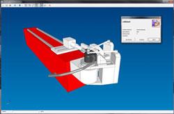
Figure 2: Simulation software not only detects a possible collision during bending, but also assists in creating a workaround to avoid the interference.
The main drawback is that the model may be too accurate and detailed. The more elements the software needs to consider, the more processing power it will require, meaning it will run slower. The 3-D models used for construction of the machine often have thousands of components, such as chain-links, O-rings, screws, and washers. They also include components inside the machine body, which are not actually relevant for interference testing. Another drawback is that these 3-D models usually do not specify the movement range and direction of the various components. And if an older machine needs to be retrofitted with independent simulation software, the original 3-D model may not be available.
An alternative method to create machine and tool models is to measure the actual machine either with a measuring system or simply by hand. Depending on the machine and the method, a detailed model of a bending machine can be created in six to eight hours. This model can even incorporate modifications from the original model, which were added by the owners. These models will be somewhat simplified in order to reduce the amount of processing power used, but still retain a level of precision required for interference testing.
Several material properties affect a tube bend. One of them is stretching, which thins the material in the bend. Stretching can be countered by boosting the tube during bending.
Another property, springback is the tendency of a tube to return to its original shape. This causes the tube’s bent angle to differ from the intended angle. The only way to compensate for springback is overbending. For example, to obtain a 90-degree bow, a slightly larger angle needs to be bent. This slightly bigger bending angle, however, also affects the length of the straight tube between bends, which will influence just how long the tube needs to be before bending commences.
Determining the required overbending angles and traction reductions to combat springback can be done in different ways. One calls for the machine to compensate automatically. Another is to use bending simulation software capable of compensating for material factors (see Figure 3). This can be done by creating a material master file that lists all materials used with their diameters, wall thicknesses, radii, and other properties. Careful test-bending of multiple tubes can populate this list so it can be used for consultation prior to bending. Another option involves using bending simulation software to interface with a CAM system, which can measure a tube bend without compensating for material properties. The result then is compared to the target data, and the software extrapolates the required adjustments.
The advantage of a material master file is that the process of test-bending tubes for measuring has to be performed only once. The downside is that it does not account for differences among batches, but instead assumes consistent quality of the material regardless of supplier. The advantage of integration with a CAM system is that this method can be used in serial production to make sure that all tubes conform to their norms, and that only one or two test examples need to be bent before fabrication can start.
One of the more time-consuming tasks for a machine operator is to calculate and enter the necessary data needed to bend the tube, especially if the operator has to adjust the data for overbending or revise the data if the bending sequence needs to be modified. The machine sits idle if there is no backlog of work, and if other stations in the shop are dependent on a continuous supply of bent tube, the machine becomes a fabrication bottleneck.
Bending simulation software usually not only calculates the data required for bending the tube, but also offers output functions that allow you to use the values immediately. An example of this is the option of printing out worksheets for each drawing, detailing the dimensions and bending values. Another option is a direct export of the CNC data in a format that machine can read. Then the file is sent to the machine—either on a USB drive or over a network—and it immediately has all the information required.
The problem with interfaces is that a manufacturer-developed application will be able to export the bending data only in the format that particular machine uses. If a shop has machines from different manufacturers, this can lead to the problem of having to use multiple parallel simulations. Independently developed software offers a little more flexibility here, because interfaces to different machine models and types can be integrated if required.
Not every application can be used for every type of machine. For example, significant differences exist between regular mandrel bending and induction bending. And the mathematics involved in freeform bending with a movable bending head are so complex and intricate that only a few applications can perform these calculations. The simulation of multihead bending machines, on the other hand, is relatively simple (see Figure 4), and most applications can perform this function.
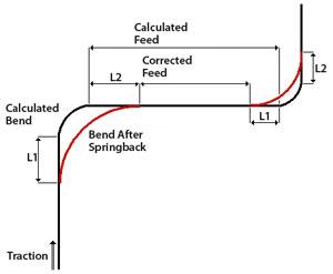
Figure 3: Creating a material master file, a detailed listing of how different tube materials react in specific bending sequences, within the simulation software can help you choose the best way to compensate for springback.
If your tube shop uses an induction or a freeform bending machine and the manufacturer does not offer a bending simulation application, the range of available software is limited to those independent developers who provide these special services.
While all simulation software products share core functionalities, such as interference detection and a graphical representation of the bending sequence, some programs offer a number of additional features.
These can include import interfaces to various drawing platforms or formats, such as IGES or PCF, so geometries do not have to be created in the simulation application itself. This is especially useful for tube shops that work as contractors because they can receive technical drawings from their customers in these formats, import and test them, and then fabricate the tubes as specified. The operators do not need the CAD platforms used for creation of the designs as long as they have bending simulation software with the right import interfaces.
Another useful feature for shops with multiple machines is the previously described multitest option, which can be very important when it comes to assigning work orders. By knowing which machine is capable of bending which tubes, you can allocate individual orders to the machines in the most efficient way possible. If the simulation software includes cycle time approximation for each machine, it also becomes possible to compare two machines directly to each other.
In a similar manner, the option to test multiple tubes can be very helpful. Some bending simulation software can extract a list of isometrics, run mathematical calculations in the background, and put out a list of the bending results for every tube, including the CNC data. This way the design department does not have to test every single drawing individually, but can test a number of pipes in a very short time.
Because it is usually easier to attach flanges to straight tubes than to bent tubes, some bending machines are capable of bending tubes with flanges. Other machines cannot chuck flanged tube ends, so if a tube that is flanged on one end needs to be fabricated, the options for alternative bending sequences are limited. Some simulation applications, however, not only can take the presence of a flange into consideration when calculating the bending sequence, but also calculate the rotation of the flanges relative to each other, which is required to make sure the flange holes on both tube ends are in the correct position after bending. This way the flanges can be attached correctly before bending, without the need for adjustments.
Finally, some tube geometries require two bends to be so close together that specially customized tooling is needed. This tooling not only has to be designed with great care, but also has to be integrated into the simulation software. Ideally, of course, the bending simulation provides the data required to manufacture the tool, saving the tool designers several hours of work while simultaneously testing the tube geometry itself. Unfortunately, very few applications are capable of this type of calculation at this time, but this may change in the near future.
While powerful bending simulation software can be very effective in increasing productivity and reducing costs, you need to be aware of some limitations.
Most important, simulations cannot replace human expertise. The simulation is only as accurate as the machine and the tool models. If the models are wrong, the simulation cannot be precise. Because of this, you always need to supervise the bending process, so you can override the results of the bending simulation if necessary.
When it comes to compensating for material properties, the software cannot account for quality differences within a batch of material. If an interface to a CAM system exists, the material factors for a new batch can be adjusted, but this always assumes that each tube in the batch shares the same qualities.
Shops also need to consider future needs as well as current ones when choosing software options. A software program today may not make sense for an expanded operation down the road.
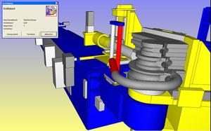
Figure 4: Simulated tube bending is not limited to single-head bending machines; simulation of multihead bending machines is also fairly common.


The Fabricator is North America's leading magazine for the metal forming and fabricating industry. The magazine delivers the news, technical articles, and case histories that enable fabricators to do their jobs more efficiently. The Fabricator has served the industry since 1970.
start your free subscription
Easily access valuable industry resources now with full access to the digital edition of The Fabricator.

Easily access valuable industry resources now with full access to the digital edition of The Welder.

Easily access valuable industry resources now with full access to the digital edition of The Tube and Pipe Journal.

Easily access valuable industry resources now with full access to the digital edition of The Fabricator en Español.
In this episode of The Fabricator Podcast, Caleb Chamberlain, co-founder and CEO of OSH Cut, discusses his company’s...


