


Tube bending basics: How to bend tubing and metal pipe
It boils down to four variables: tube material, tooling, lubrication, and the machine
Regardless of whether you’re working with tube or pipe, and regardless of the bending process, making the perfect bend boils down to just four factors: the material, machine, tooling, and lubrication.
Editor’ Note: This article is based on the Tube Bending 101 FabCast, facilitated by the Fabricators & Manufacturers Association International (FMA) and presented by Danie Jacobs, president of i-Fab LLC.
Many call tube bending a black art, a mysterious process with unavoidable trial and error. But in reality, the basic principles have remained the same for decades. The technology used to bend tubular workpieces has evolved significantly, but all the mechanical magic can’t alter physics.
Regardless of whether you’re working with tube or pipe, and regardless of the bending process, making the perfect bend boils down to just four factors: the material, machine, tooling, and lubrication.
Tube Bending Fundamental Terms
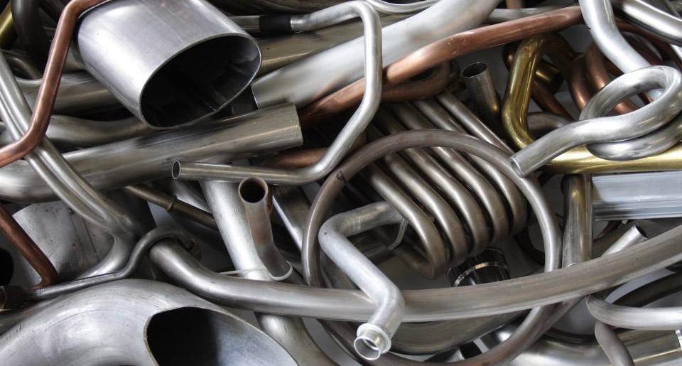
Bending starts with knowing the properties of the tube or pipe you’re working with. Pipe, usually used to transport fluid or air, is specified by its nominal pipe size (see Figure 1). But when you’re specifying a bending machine, the centerline radius, the outside diameter, and wall thickness are critical variables.
Also, every pipe schedule has a nominal wall thickness. There’s a tolerance, and the wall thickness can vary slightly. This variation should be accounted for, especially for bending processes using precise, tight-fitting tooling on small bend radii.
Other bending variables include the inside bend radius (sometimes called the intrados); the outside bend radius (or extrados); and the centerline radius or the neutral line, where neither compression nor stretching occurs. The bend angle refers to the complementary angle of bend. So if a tube is bent to “45 degrees,” that’s 45 degrees complementary, or a 135-degree included bend angle (see Figure 2). The distance between bends (DBB) is just what it says. More specifically, it’s the distance between two tangent points, where a straight section begins to curve and the bend starts or finishes.
Like in press brake forming, tubes experience springback after bending, producing a bend that undergoes radial growth. Generally speaking, the harder the tube and the smaller the bend’s centerline radius, the greater the springback and resulting radial growth. Copper undergoes less radial growth than steel, which has less springback than stainless steel.
Although some are seamless, most tubes are produced with a longitudinal weld. In tube bending, the quality, size, and consistency of that weld seam matter. If the two edges of the joint don’t align perfectly, or if the weld bead is too large or inconsistent, these discontinuities will affect the tube’s roundness. That creates problems if you want to create the perfect bend.
Elongation occurs during bending, and the outside radius stretches (causing wall thinning), which the material resists. This causes the outside surface of the bend to cave in, causing ovality, or a distortion of the cross section from its original round shape. Some ovality is acceptable for certain applications, but unacceptable for precision work. That’s because as the outside stretches, the inside radius compresses and at a certain point starts to wrinkle.
Like any other manufacturing technology, the application requirements drive the fabrication method of choice. Specialty tube bending processes abound, some old and some new. Most tubes, though, are bent one of four ways: ram-type bending, roll bending, compression bending, or rotary draw bending.
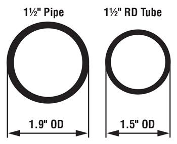
Figure 1
Pipe is specified by its nominal pipe size, while tube is specified
by its outside diameter.
Ram-type Bending
Visit any muffler shop and you’ll probably see a ram-style bender (see Figure 3). One of the oldest and simplest tube bending methods, it uses a hydraulically driven ram that forces a tube against rollers or pivot blocks. You generally can achieve a centerline radius (CLR) that’s three to four times the workpiece OD.
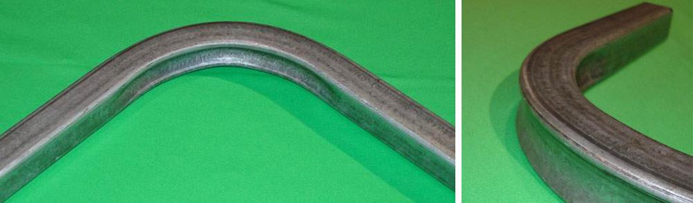
The workpiece ID isn’t supported, and a substantial amount of stretching occurs on the outside of the bend. This method is popular in square tubing applications, for which many design the ram tool so that it deliberately compresses and slightly deforms the inside bend radius (see Figure 4). This prevents wrinkling and forces the outside surface of the bend inward, producing a concave surface and preventing excessive stretching on the outside of the bend.
This process is by far the least expensive way to bend tube and pipe, but it’s not as controllable as other methods. If workpiece cosmetics are important or the application has tight bending tolerances, the ram-type method may not be the best choice.
Roll Bending
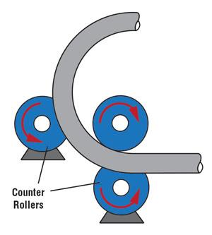
Commonly used for large workpieces in construction, roll bending generally entails three rolls positioned in a pyramid, oriented either vertically or, for larger sections, horizontally. The rolls move to produce specific, usually very large radii. Which rolls move where depends on the machine. On some, the top roll moves up and down to produce the desired angle; on others, the two bottom rolls move and the top roll remains stationary (see Figure 5).
Another machine type is the two-roll, pinch-style roll bender. For this system, the tube feeds between an upper and lower roll, while on either side two adjustable guides move to produce the desired bend angle.
Many use roll bending to produce spirals. If a workpiece has a one-diameter pitch and a large radius, the operator can lift the tube after one revolution to produce a continuous coil. Some applications, including those with a larger coil pitch, require an additional roll that guides the tube outward as the coil is being formed.
Compression Bending
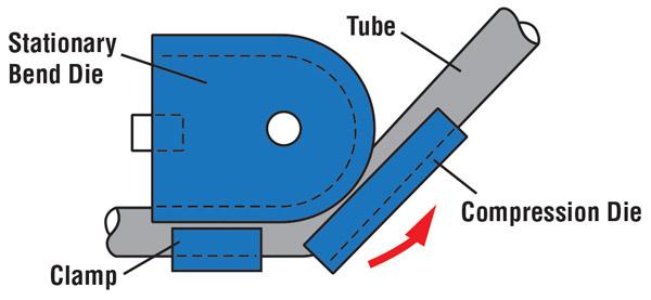
Compression bending uses a roller or compression die (sometimes called a follow block) to bend the workpiece around a stationary bend die (Figure 6). The system clamps the workpiece just behind the rear tangent point. The roller effectively “compresses” the tube against the central bend die. This method is most common in symmetrical workpieces—those with identical bends on either side—often bent in one setup on a machine with two bending heads. This method works well for tubes bent to a CLR that’s at least three times the tube OD.
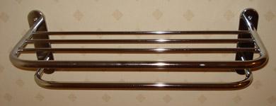
The bend’s outside surface may flatten slightly because the tube ID is not supported. It’s not recommended for workpieces with a CLR less than three times the tube diameter. This method is used mostly to produce household and commercial products. If you see a towel bar with two identical bends on each side, it was probably formed with compression bending (see Figure 7).
Rotary Draw Bending
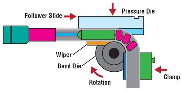
For precision work, rotary draw bending dominates the tube bending landscape, especially for those applications involving tight radii—sometimes down to a CLR that’s just 0.7 times the tube OD (or as tube processors call it, less than 1×D). This process gives you maximum control over wall thinning and ovality. Rotary draw bending supports the flow of the material during bending using a mandrel in the tube ID and precision tooling on the outside (see Figure 8).
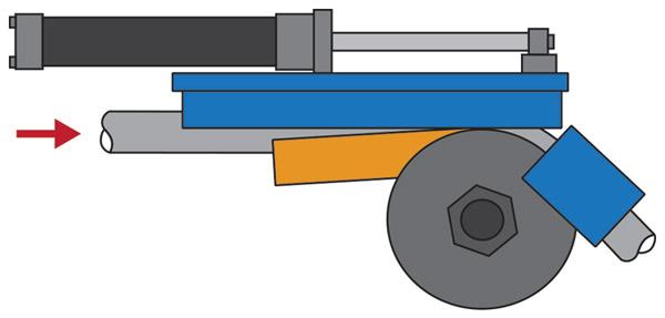
A rotary draw setup entails a pressure die that holds the straight section (sometimes called the tangent) of the tube; a clamp die that rotates the workpiece around a round bend die; a mandrel, sometimes with a series of articulating balls on the end to support the tube interior around the bend; and a wiper die that contacts the workpiece just before the tangent point of the inside radius, wiping against the material to prevent wrinkles that can form on the bend’s inside radius.
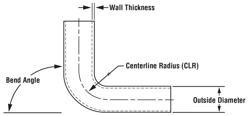
Figure 2
A bend angle in tube bending usually is calculated from the outside—the complementary bend angle. Other critical dimensions
are the wall thickness (which thickens on the inside radius and thins on the outside radius) and outside diameter.
The pressure die (also called a pressure slide) supports the outside radius during bending. The pressure die can be stationary; it can follow the workpiece, sliding on rollers at the same rate the workpiece is being drawn into the bend; or it can be “boosted,” pushed with hydraulics or (more common today) electrical servomotors, further minimizing wall thinning. All these elements effectively control both the tube ID and OD throughout bending.
Tube Bending Tooling
To achieve the perfect bend, you need a good tooling setup, and nowhere is this more critical than in rotary draw bending. Consider the mandrel—its hardness matters. If you have a hard tube and a hard mandrel, or a soft tube and soft mandrel, the mandrel will tend to stick inside the tube and wreak havoc on the process. As a rule of thumb, make sure you have a combination of hard and soft material. If you have a hard workpiece, you need a soft mandrel; if you have a soft workpiece, you need to use a hard mandrel.
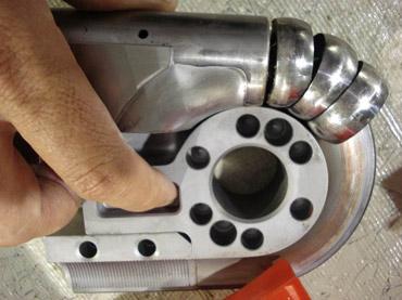
Your tooling also should take radial growth into account (see Figure 9). If radial growth is excessive, the nature of the rotary draw process means that after the clamp die releases, the radius at the beginning of the bend will be noticeably different from the radius at the end of the bend. To accommodate for radial growth, particularly if it involves hard material and a 3×D CLR or greater, you may need to use a bend die with a smaller radius.
Draw bending also requires a good tube with good welds. An inconsistent weld bead protruding into the tube’s inside or outside surface will wreak havoc on the mandrel, pressure die, and wiper die.
Regarding the wiper die, its position is critical (see Figure 10). The die should be angled slightly (a little off parallel with the tube) so that its end contacts the tube just before the inside radius tangent point—a transition that’s the workpiece’s weakest point during bending. The condition of the wiper die’s contact point is also critical. It should be sharp to the touch. The wiper die can wear over time, so for some jobs, it is good practice to keep a spare wiper die available.
As for the clamping die, its length should be three times the tube diameter. Occasionally some technicians shorten this length to two times the tube OD, but this isn’t usually recommended. The clamp die clamps the workpiece to the bend die and holds the tube as it is drawn around. The shorter the clamp is, the more pressure it puts on a short section of the workpiece, thus increasing the risk of deforming it. A clamp die that’s at least three times the workpiece diameter spreads the pressure over a larger area.
This clamping die requirement can create challenges when you are forming a workpiece with short distances between bends, but special tooling can overcome this. It usually comes in multi-stacked arrangements, common on some of today’s CNC bending systems. In this arrangement, you have a stack of two or three (or even more) clamp dies. One is a traditional clamp die used for holding straight sections, and the other—called a form die—is machined to a specific shape so it can clamp to previously formed bends. (These advanced systems also can have stacks of bending dies for different tube radii, so an operator need not change out tooling between different jobs.)
Certain tubes, especially those with thin walls, require a series of balls that can flex on the end of the mandrel, supporting the tube ID in the bend itself. The positioning of those balls matters during machine setup. Normally, you should place a mandrel so that the series of balls start at the bend’s beginning tangent point; you then move the mandrel slowly forward until a quality bend is achieved, but not too far—especially for ultrathin-walled tubing. If the mandrel is moved too far forward, some of the balls actually may break off inside the tube during bending (see Figure 11).
Lubrication Factors
A mandrel with articulating balls fits tightly within the tube ID. The clearance between the mandrel shank and tube ID is only about 0.009 in.; the clearance between the balls and tube ID may be a little larger, but not by much. Such a tight fit would cause significant friction without the right lubrication.
Nonpetroleum-based synthetic lubricants are becoming more popular. Often supplied as a paste or gel, they can be diluted to whatever consistency the application requires. Generally speaking, heavier-duty bending with thick walls and tight radii requires more concentrated lubrication. Wiper dies also need to be kept properly lubricated at the contact point to prevent premature wear.
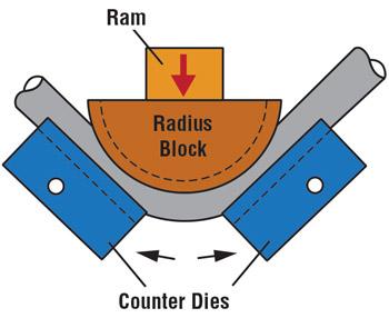
Figure 3
Ram bending is one of the oldest, simplest, and least expensive
types of tube bending. But it is not as controllable
as other processes.
Good Machine
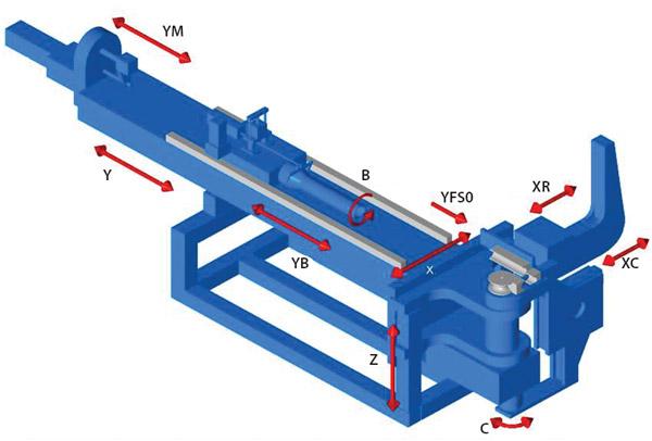
For rotary draw bending, more all-electric machines are finding homes on tube shop floors. And with such machines comes more available axes of control—all important when specifying a machine. A CNC machining center may have five axes. In CNC tube bending, you sometimes must consider up to 10 axes (see Figure 12). Some of the most common axes are:
Y: Distance between bends
B: Plane of bend rotation
C: Bend angle
X: Horizontal shift of the workpiece
Z: Vertical shift of the workpiece
XR: Reaction slide
XC: Clamping motion
YB: Boost motion
YM: Mandrel motion
YSFO: Follower pressure die motion
In machining, of course, axes can move simultaneously, but in tube bending, machines work with “stalled axes,” meaning that each axis stops momentarily before moving on to the next. In one complex application, for instance, the workpiece may be moved forward for the first bend (Y); the mandrel moved into position (YM), clamped (XC), and then bent (C, YB, YSFO). It’s then unclamped (C), and moved again into position (Y). The workpiece may be rotated, changing the plane of bend (B). Subsequent bends may require the remaining unbent tube section to shift (X, Z).
Some newer machines actually have space for tooling to combine bending processes. For instance, say you have a part that has several tight-radii bends as well as one large-radius bend. Building a bend die that large for rotary draw bending wouldn’t be practical. That’s why some machines offer roll bending along with rotary draw bending in one unit.
Machinery requirements hinge on various factors, including material grade, wall thickness, workpiece, and the CLR you need to achieve. As always, you should use information from your machinery and material suppliers to determine application-specific requirements.
The Art and Science of Tube Bending
The capability of modern machines, combined with the latest software and controls, shows just how precise tube bending has become. True, material variability and certain application-specific challenges make some level of unpredictability unavoidable. Nevertheless, with the right material, tooling, lubrication, and machine, you have a much better chance of achieving the perfect bend—every time.
About the Publication

subscribe now

The Fabricator is North America's leading magazine for the metal forming and fabricating industry. The magazine delivers the news, technical articles, and case histories that enable fabricators to do their jobs more efficiently. The Fabricator has served the industry since 1970.
start your free subscription- Stay connected from anywhere

Easily access valuable industry resources now with full access to the digital edition of The Fabricator.

Easily access valuable industry resources now with full access to the digital edition of The Welder.

Easily access valuable industry resources now with full access to the digital edition of The Tube and Pipe Journal.

Easily access valuable industry resources now with full access to the digital edition of The Fabricator en Español.
- Podcasting

In this episode of The Fabricator Podcast, Caleb Chamberlain, co-founder and CEO of OSH Cut, discusses his company’s...
- Trending Articles
1
Tips for creating sheet metal tubes with perforations

2
Are two heads better than one in fiber laser cutting?

3
Supporting the metal fabricating industry through FMA

4
JM Steel triples capacity for solar energy projects at Pennsylvania facility

5
Omco Solar opens second Alabama manufacturing facility
