


President
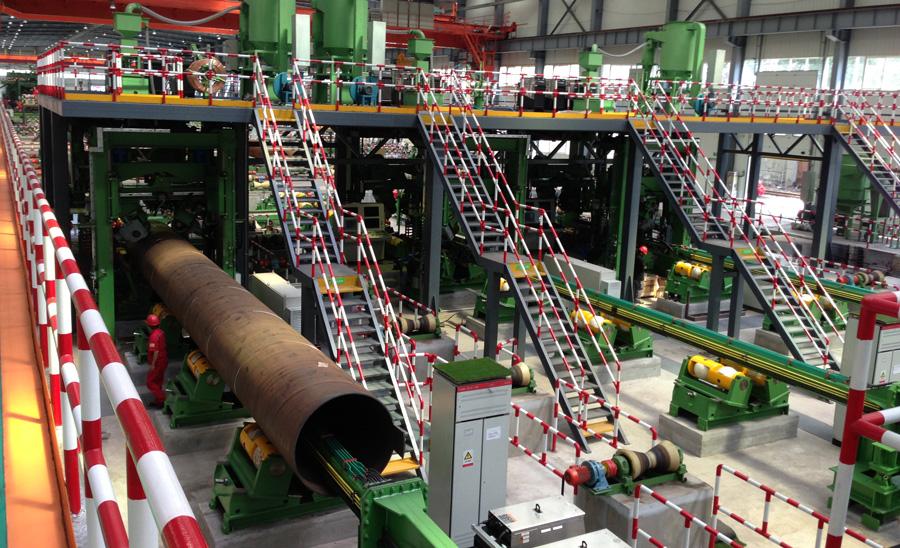
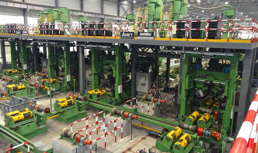
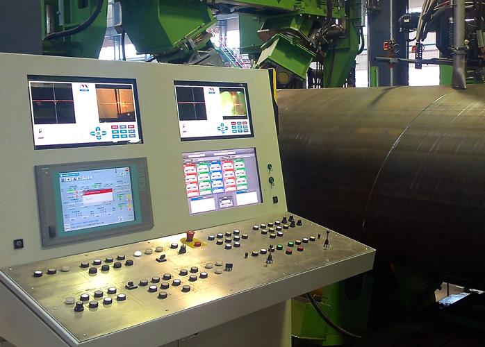
Figure 1
This two-step spiral pipe mill uses several automated submerged arc welding systems. A pipe mill with this design separates pipe forming from final welding, which allows the pipe to be formed and tack welded at very high speeds.
As the demand for spiral pipe for the petroleum industry has increased, so has the desire for fabrication systems that can provide shorter weld cycle times, higher throughput, and reduced material consumption. The demand is driving significant advancements in automation—especially in welding.
Spiral pipe fabricators use multitorch submerged arc welding (SAW), which provides high deposition rates, accommodates thick pipe walls, and produces high-quality welds. This is welding-intensive work, and fabricators need high quality and speed to compete. Automation has helped provide both.
Pipe mills can produce longitudinally welded pipe with outside diameters (ODs) of up to about 42 inches. Larger diameters require wider plates, which makes traditional pipe mills less cost-effective. Such pipe is therefore typically produced in spiral pipe mills, where the pipe diameter is no longer a function of plate width.
This doesn’t mean that spiral pipe mills can’t handle pipe with ODs less than 42 in. To the contrary, today’s faster and more flexible spiral pipe mills can produce smaller-diameter, thicker-section pipes, such as those having a 15.7-in. OD and 0.39-in. wall thickness.
There are two types of spiral pipe mills: a one-step and a two-step (see Figure 1). Each has pros and cons related to initial capital investment, production requirements, facility size, operating costs, and other factors. Regardless, both have made more use of automation to improve quality and output.
As its name implies, a one-step spiral mill process forms and welds the pipe in one step. The incoming steel coil, called a skelp coil, is unwound, flattened, trimmed, and squared, after which a joint profile is completed. The now edge-prepped steel is then fed into the mill at an adjustable angle, or helix angle, which determines the final pipe diameter.
The plate is formed into a continuous spiral tube. As the mill bends the incoming strip and the edges are brought together under the inside-diameter (ID) weld head at the 6 o’clock position, the ID weld head performs SAW. The pipe continues to rotate and progress through the mill, and at the 12 o’clock position the OD head performs the outside weld (see Figure 2). One coil end is fusion welded to another, making a continuous coil feed into the spiral mill. Although the mill can form the pipe at high speeds, the output of the mill depends on the speed of the SAW process.
A two-step spiral pipe mill separates pipe forming from final welding, which allows the pipe to be formed and tack welded at very high speeds. The initial process essentially is the same as the one-step method, except as the plate is formed into a continuous spiral pipe, a separate welding operation—usually automatic gas metal arc welding (GMAW)—performs a tack weld, which maintains the pipe’s dimensional integrity as it’s transferred to the final spiral welding station.
Like in the one-step operation, the two-step process uses SAW on the ID at the 6 o’clock position. In a two-step operation, though, this pass also remelts and covers the GMAW tack. Then the subsequent SAW pass on the OD at the 12 o’clock position remelts the root of the ID pass and completes the joint.
To increase weld deposition and production speed, most spiral pipe mills use multiple SAW torches that feed into the same pool. Typical systems have two torches for the OD and three torches for the ID. The leading arc can require so much power that additional power supplies need to be paralleled together to supply it (see Figure 3).
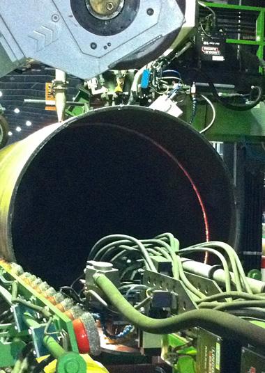
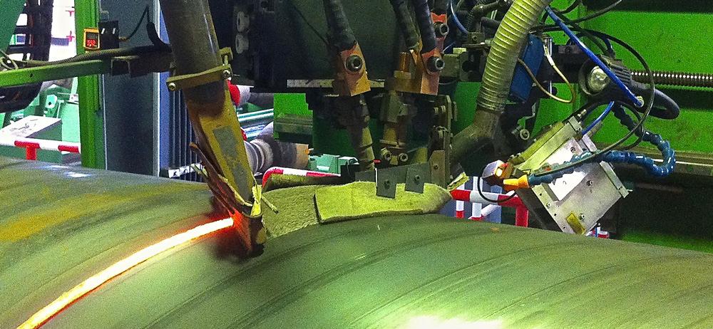
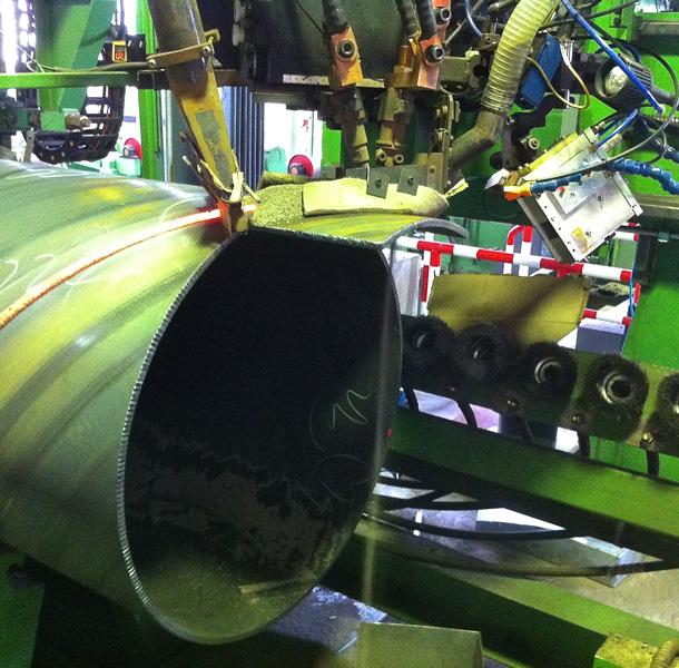
Figure 2
In this spiral pipe welding setup, a SAW head welds the ID (at the bottom) while a separate head welds on the OD (at the top).
The welding process relies significantly on various functions of the mill. The one-step mill has functions to control the feed rates (welding travel speed) as well as the resulting gap and joint mismatch as the plate is welded. The offline weld station in the two-step process also provides the necessary feed and rotation for the weld travel speed.
Automating all this isn’t trivial. Its success hinges on the integration of various components, with laser sensors feeding back information that can be used to perfect and refine the system as a whole. This ultimately is what produces higher-quality products at faster rates. Advances in four specific areas make it all possible: the welding heads, laser sensors, welding power supplies, and process monitoring and integration.
Successful spiral pipe welding begins with precision welding heads (see Figure 4). Today’s torch heads are compact, dense, rigid structures that incorporate heavy-duty slides, wire feeders with redundant straighteners, video cameras, laser sensors, and flux delivery and recovery systems.
The ID head must not only be compact to fit into the smallest desired pipe ID, but also rigid to maintain dimensional stability at high temperatures for long periods. Often constructed of composite materials, these rugged welding heads are designed to withstand harsh conditions inside the pipe. Their frame is designed for rigidity, current transfer, and heat dissipation. The heads’ materials and components provide structural integrity, thermal stability, and electrical conductivity, as well as isolation and contamination protection from the SAW process and overall pipe mill environment.
The heads incorporate multiple wire feeds in compact configurations to accommodate small IDs. A critical feature of the ID head, wire delivery must reliably feed multiple wires around a 90-degree bend in the constrained space. Weld quality and process stability depend significantly on how effectively and smoothly the wires are delivered to the weld pool.
In older systems, welding heads moved using pneumatics or basic mechanical or motorized devices. Today, though, servomotor and encoder-based systems move the heads precisely to the optimal position. All this, combined with sealed precision slides, helps position the weld heads accurately and quickly as they follow the joint. The head’s velocity also adjusts as it reacts to necessary position changes. Being servo-controlled, the cross-seam and height-position slides ensure the welding wires feed at the right place relative to the weld joint.
Precision welding heads are like a finely tuned muscle, able to deposit weld metal at just the right place and at just the right time, but they won’t know where or how to move without vision—that is, a real- time laser-based sensor system. Integrated with the welding head and mill control systems, laser sensors allow the automation to adaptively control both the head position and fit-up during welding and tacking.
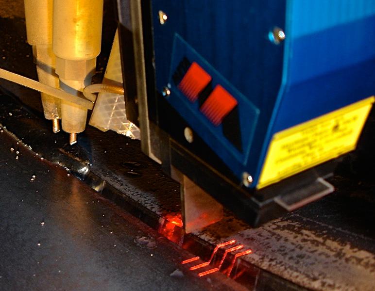
These noncontact laser sensors continuously feed back information about changes in joint characteristics. Being positioned ahead of the welding torches, the laser projects horizontal stripes across the joint; in turn, a camera “reads” the characteristics of those stripes to obtain information about the cross-seam position and height, along with other details about the joint profile (see Figures 5 and 6). It then uses this information to modify control aspects of the welding or mill forming processes.
Because the one-step and two-step setups need different kinds of information, each has its own approach to laser sensing. Regardless of the setup, though, laser sensing starts when the two base metals come together. In the one-step process, this occurs when incoming material comes together to form the weld joint. During the first step of the two-step operation, laser sensing starts when the material comes together to be tacked. At this point it’s important to know not just where the joint is relative to the weld head, but also if the gap and mismatch is being controlled adequately.
In the second step of a two-step operation, single-stripe laser sensors can provide position, height, and feature information. Using the laser, the system can automatically identify the run-on and run-off tabs (to facilitate weld starts and stops) attached to the tack welded pipe. It can use that information to feed the pipe to the start position, locate the joint, position the weld heads, start the flux delivery, and initiate the weld; and when the laser detects the run-off tab, the system then knows when to stop welding. This effectively automates the entire feeding and welding operation, from delivery of the tack welded pipe to the weld station through the end of the final weld (see Figure 7).
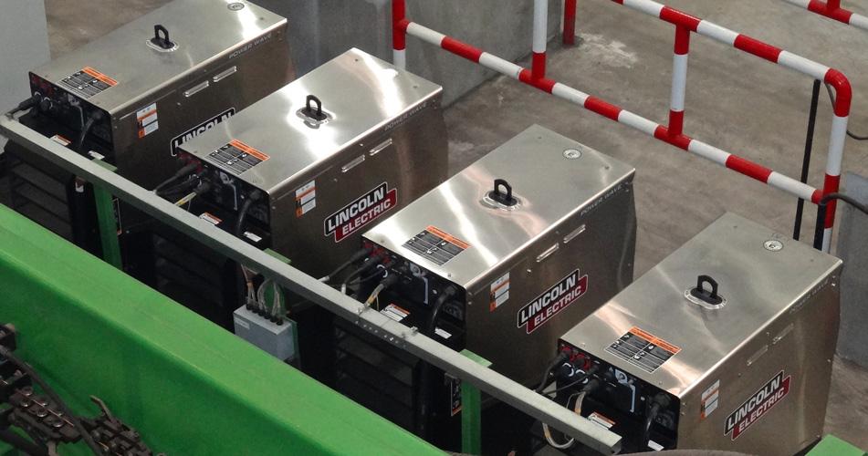
Figure 3
These four power supplies from Lincoln Electric are integrated with a three-torch ID head. Two of the power supplies are paralleled to provide up to 2,000 amps to the lead SAW torch.
When the ID environment is not conducive for laser sensing, or if the ID is just too small, the sensor can run separately from the weld head. In these cases, the sensor can be mounted on a separate set of servo-driven slides on the OD, directly opposite the ID torch assembly. The ID head slides are then electronically slaved to the sensor OD slides, mirroring the movements so that both the sensor and weld head follow the joint and maintain the programmed height.
All these process control efforts would be for naught without consistent and reliable power delivered to the wire contact tips for long durations. In these applications, SAW can demand more than 700 amps per power supply for several hours. It requires both accurate DC and AC output and the ability to switch between modes for different pipe products. The most advanced supplies can compensate for variances in power input, temperature, and power demand to ensure a consistent and stable output.
Digitally controlled inverter power supplies have opened automation possibilities in difficult welding situations. These power supplies have become an integral part of the complete system, all accessed from a single controller. From that controller, the operator can enable or disable the power supplies; change modes between DC and AC; and vary current, voltage, and AC phasing—all based on part type or even the torch position. This helps shorten the setup and cycle time significantly and improve reliability.
Such a complex automated system—complete with servo-controlled weld heads, multiple wire feeders, advanced laser sensors, and more—can overwhelm the most experienced engineers and operators. If all the elements weren’t integrated with process quality and repeatability, ease of use, and errorproofing in mind, even the most sophisticated welding system would cause costly errors.
In traditional approaches, a start or change of any given component was activated, or linked, together with the start or change of another component. For example, the process may start with the operator pushing the start button on the pipe mill feed, which would activate the flux delivery control, and then after several seconds activate the controls for the power supplies, beginning the weld.
A change in the part thickness would most likely require dialing in new settings on several or all controllers. Unfortunately, this communication typically occurred in one direction. If someone dialed in an incorrect setting for one component, there was no way for that information to be communicated automatically to other elements in the system. The automation would continue on blindly, unaware of the incorrect parameter, which of course led to problems.
Modern integrated controls and process monitoring have overcome these challenges. Consider a typical PC network in an office setting, and how each person in a work group has his or her own computer to perform a task. If the computers are networked, then everyone working on the same project can share all of the relevant information and respond to others on the same network.
The latest approaches to complex automated control now are based on the same technology. Dedicated processors control and monitor each task and share the information over a network so that other, appropriate system components can respond or react.
Distributed processor control has many advantages for complex systems that require many tasks to be programmed, controlled, and monitored. All parameters for each weld or part type can be programmed, stored, transferred, and displayed through a single controller on the network. This dramatically shortens setup time and reduces the chance for operational errors.
Such controllers or modules use digital signal processors (DSPs)—the same platform used by cell phones and other electronics we use every day. DSPs allow one system component to share information and have other components in the system respond—a deceivingly simple yet critical function that has allowed automation to expand into new areas.
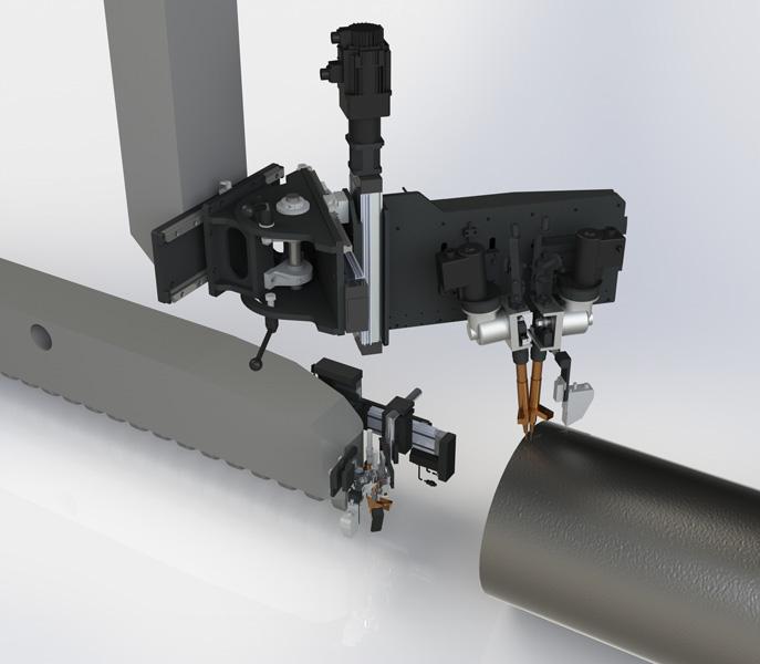
Figure 4
This spiral pipe welding head assembly helps incorporate heavy-duty slides, wire feeders with redundant straighteners, video cameras, laser sensors, and flux delivery and recovery systems.
It’s also what has allowed elements in automated spiral pipe welding to respond and adapt the way they do. The welding automation responds to feedback not just from the laser sensor, but also from the servo position of the head, mill feed, weld station rotation, and the preset contact tip-to-work distance. Gathering and sharing data from all these points allow the automation to maintain the required joint centerline position and torch height. Other sensors can be integrated as well, including sensors for temperature measurement.
The automation can vary any of the process parameters according to the position of the torch or part, monitor each system component continuously, provide process data, and alert the operator about out-of-tolerance conditions. In addition, the controller can automatically program the start of flux delivery as well as the position of the weld head, part feed-in and delivery, and other desired functions or moves before or after the weld.
Connected to a network, the controller sends performance data to a central station in the plant, where technicians can monitor multiple welding systems, transfer programs and data between those systems, and compile information for overall plant production and quality performance (see Figure 8).
Of course, no matter how advanced and intelligent the automation is, it isn’t very useful if only highly trained technicians can program it or access its data. Modern systems allow operators and engineers to select and enter desired values without knowing a programming language. Controllers include not only displays, but also joysticks, knobs, and buttons with tactile feedback. This allows operators to keep their focus not on programming, but on the process itself (see Figure 9).
Historically, the welding community has struggled to implement new technologies, especially in complicated environments with myriad variables. Regardless, industry demand—the latest oil boom included—is pushing spiral pipe production toward sophisticated automation. Ultimately, advances in electronics, processing capability, laser sensors, current control, and network communications are driving significant changes, even in the most challenging applications.


The Fabricator is North America's leading magazine for the metal forming and fabricating industry. The magazine delivers the news, technical articles, and case histories that enable fabricators to do their jobs more efficiently. The Fabricator has served the industry since 1970.
start your free subscription
Easily access valuable industry resources now with full access to the digital edition of The Fabricator.

Easily access valuable industry resources now with full access to the digital edition of The Welder.

Easily access valuable industry resources now with full access to the digital edition of The Tube and Pipe Journal.

Easily access valuable industry resources now with full access to the digital edition of The Fabricator en Español.
In this episode of The Fabricator Podcast, Caleb Chamberlain, co-founder and CEO of OSH Cut, discusses his company’s...


