


Field Tech Support Specialist
Implementing an effective robotic welding cell layout requires careful planning and attention to detail.
Today, even the smallest weld shops are making the jump to robotics, and even the largest, highly automated OEMs likely have semiautomatic weld cells for repairs or for welding parts that don’t lend themselves to automation. In automotive manufacturing, these manual cells may be midway through the line for welding frames or at the end for minor rework. If you’re in heavy equipment manufacturing, you might automate multipass welding on thick parts and reserve semiautomatic welding for tacking the parts or adding specialized components.
No matter your industry or your level of welding automation, an effective weld cell layout can help. Work needs to flow in an orderly fashion. Power, grounding, and wire feed cables need to be properly managed. And, of course, you need to ensure welders can work safely, consistently, and with good ergonomics. Proper layout supports high productivity and quality, along with cost savings.
Whether robotic or semiautomatic, a well-designed weld cell makes efficient use of available space, where every component—the power source, welding gun, weld table, cables—ensures parts can be produced with little interruption. Streamlining workflow is a good first step. This involves setting up equipment in a way that helps operators avoid handling parts multiple times. Double handling of parts adds non-value-added seconds to the overall manufacturing cycle time and reduces the capacity for completed parts sent out the door. Think with an assembly line mentality.
Look beyond the weld cell to how parts are being delivered. For example, when an operation requires that parts receive semiautomatic tack welds before robotic welding, work must flow at a consistent pace to prevent the welding robot from sitting idle. To ensure a steady supply of parts and prevent bottlenecks, the cell should have a single point of entry. For optimal workflow, parts should move out of the weld cell in the same direction.
Minimize the distance a part needs to travel by keeping assembly points close together. Weld cells contributing to the completion of a single weld assembly should be in the same area of the facility. This proximity not only reduces time for moving a part, but it also lessens the number of footsteps operators need to make. Excessive movement in a welding cell is considered non-value-added work.
If you notice bottlenecks or operators or welding robots standing idle, or operators walking too far between weld cells, you might consider performing an audit. Any idle operation results in a failure to capitalize on the investment of that process. An audit can help you identify the causes behind these problems and implement solutions. The aim is to balance out the operations so that every aspect contributes to value-added work and high productivity.
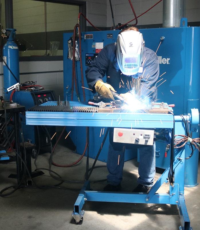
Welding ergonomics are at the center of a semiautomatic welding cell layout. A more comfortable, healthier welding operator is a more productive one. Setting up the weld cell in a way that minimizes the need to reach repetitively or move awkwardly can reduce the risk of work-related musculoskeletal disorders.
Try to position the workbench or workpiece between the welding operator’s waist and shoulders, since this promotes a neutral posture that reduces stress on the body. When welding large components, use positioners or weld tables that move or rotate the part to the correct height and angle.
The same holds true when providing operators with a MIG gun that suits them, whether it be a curved or straight handle. Locking triggers help support comfort, as do rubber mats to stand on.
Strategically locating the power source and wire feeder can make the cell more efficient. Keep the two pieces of equipment as close as possible, so the operator can easily access them. Close proximity allows for shorter power cables for smoother wire feeding and also reduces electrical resistance drops so welding parameters remain more consistent.
Position the workbench or workpiece between the welding operator’s waist and shoulders, since this is a neutral posture that reduces stress on the body.
Keep ground cable connections to a minimum. Some companies string together welding cables between weld cells for the same power source. This practice is inefficient, however, and can lead to problems. The multiple junctions can wear out easily, which causes electrical resistance and poor weld quality over time. The electrical resistance also can shorten consumable life, resulting in erratic arcs and burnbacks, leading to more downtime for contact tip changeovers.
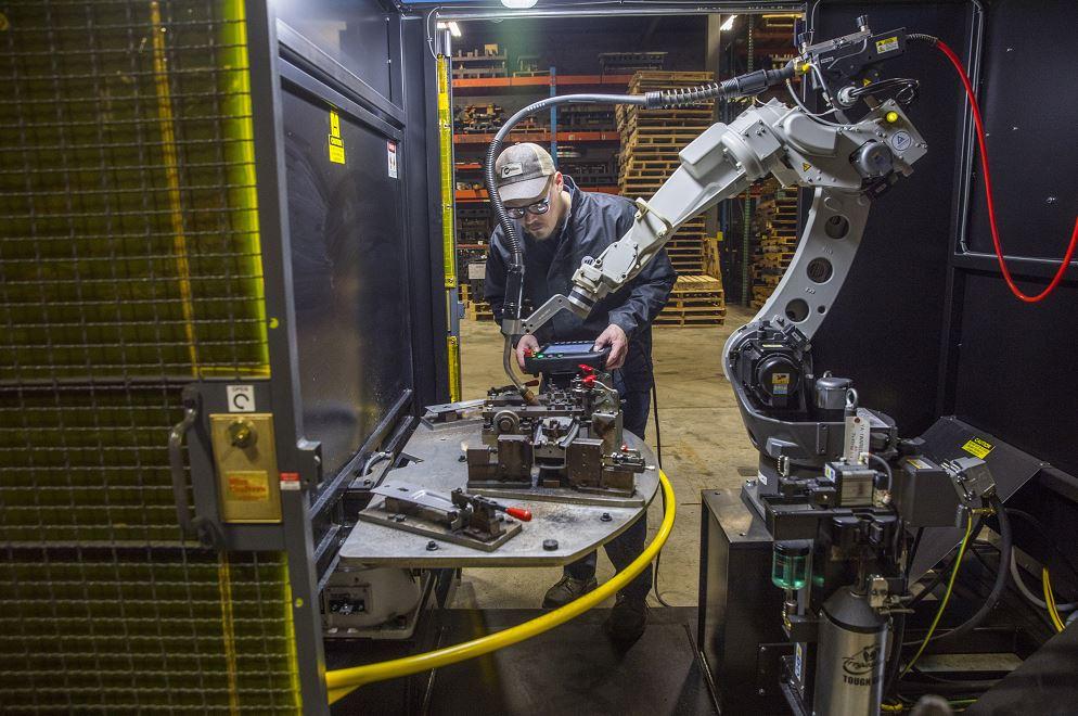
Implementing an effective robotic welding cell layout requires careful planning and attention to detail. One of the best approaches is to test the layout through virtual modeling or 3D simulation. These software programs can simulate the welding gun configuration—neck length, nozzle, and mounting (solid versus clutch)—to ensure it will operate properly within the work envelope. They also consider weld sequencing, robot arm movement, fixturing, and the parts to be welded so that you can be confident everything will work as planned.
Take the time to simulate the weld cell layout and process before equipment integration to avoid issues once the welding robot is in service. Simulations help prevent downtime during mass production for troubleshooting and potential expenses for revamping tooling or replacing components.
They also can model another key factor—welding robot reach. Be sure to match the size of the part with the reach of the robot. The robot must be able to reach all weld joints on the part; otherwise, you might need multiple robots for the application. A single, small welding robot won’t suffice for welding on a large part. If you have a weld on the edge of the reach envelope, you might not be able to achieve the optimal welding gun angle to create quality welds. This can add costs for rework, and you’ll likely need to replace stretched power cables that fail prematurely.
Regarding tooling, you might be tempted to purchase less expensive options—though such tooling might not have the features you need, such as the appropriate number of clamps or location pins. This can lead to inconsistent part fit-up or locating that requires multiple passes to fill the weld joint, adding to cycle time. You might experience more downtime as you reprogram the welding robot to accommodate the gaps, or you may end up needing to invest in touch sensing to locate the joint. Even worse, you might need to upgrade your tooling after the initial design phase—a costly step.
Also consider the positioners. Their size and weight capacity must account for both the weight of the part and the tooling. Design the robotic cell for the heaviest part to be welded.
Where you place the power source and wire feeder matters as they both impact power cable management and grounding. If space is at a premium, you may want to place the welding power source above the robot cell on a mezzanine. This way, you can run the power cable and ground leads down channels in the cell’s back wall directly to the tooling and welding robot.
These leads are stationary—except for the ones on the robot, so be sure to account for the robot’s air movements to minimize wear on the cables. Placing a junction power block at the base of the robot and running a high-flex power cable from that base up to the wire feeder can help save time in repairs, and it can save money. If the high-flex cable becomes worn, you just replace that shorter piece instead of the entire cable. The same approach works for the grounding leads.
Finally, determine the best location for the nozzle cleaning station or reamer. This peripheral cleans the nozzle of spatter during routine pauses in welding. It helps extend consumable life and reduces downtime for changeover.
The reamer needs to be close enough for the robotic welding gun to engage fully for the ream cycle. If you’re operating two robots close together, you can program them both to use the same reamer. Avoid mounting the reamer anywhere but a flat surface, since positioning it at an angle can cause anti-spatter to leak over equipment or fixtures.
Avoid interrupting the weld cycle by cleaning the nozzle during robot idle time. For example, consider cleaning the nozzles while parts are being transferred in and out of the fixture or while components are being loaded into a weld cell.
If you’re experiencing bottlenecks or missing productivity or quality goals, take a look at the welding cell layout. In a semiautomatic setup, never overlook welder comfort and safety. In a robot cell, moving power cables, power sources, wire feeders, or anything else can change how much that cell can produce over a shift.
The little things matter, and missing just one detail can snowball into bigger problems down the road. Small changes can make a big impact on the efficiency you can achieve.


The Fabricator is North America's leading magazine for the metal forming and fabricating industry. The magazine delivers the news, technical articles, and case histories that enable fabricators to do their jobs more efficiently. The Fabricator has served the industry since 1970.
start your free subscription
Easily access valuable industry resources now with full access to the digital edition of The Fabricator.

Easily access valuable industry resources now with full access to the digital edition of The Welder.

Easily access valuable industry resources now with full access to the digital edition of The Tube and Pipe Journal.

Easily access valuable industry resources now with full access to the digital edition of The Fabricator en Español.
In this episode of The Fabricator Podcast, Caleb Chamberlain, co-founder and CEO of OSH Cut, discusses his company’s...


