


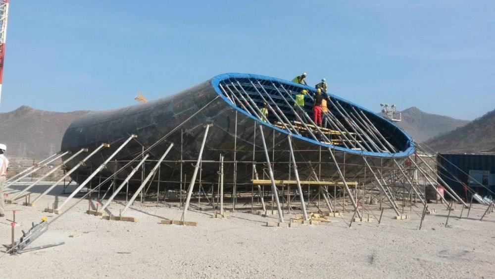
Building a draft tube form for a hydroelectric dam
Vast tubular structure comprises thousands of irregular shapes
Programmable and versatile, robots often are used to perform a manufacturing process. When faced with a difficult manufacturing challenge, engineering firm Wenlock Ltd., Shrewsbury, U.K., figured out a way to use a robot for fixturing components for assembly.
Your phone rings. It’s a call about a bid on a fabrication job, and it sounds straightforward. The person on the other end of the line wants you to build something like a steel box. Not exactly a box, but a box with open ends. It’s to be made from six pieces of plate—a top and a bottom, two sides, and two supports that run parallel to the sides. When finished, the box is to be 24 in. tall, 30 in. wide, and 36 in. long.
You need to cut the parts, fixture them, weld them, and clean up the edges. Sounds easy.
Well, it’s not quite that easy. The customer needs boxlike structures that have other designs and sizes, some consisting of up to 14 individual components, and then eventually you’ll have to join one to the next, and the next, and the next.
An assembly of steel boxes. Got it. No problem.
But as the customer starts to describe the project in more detail, it becomes more complicated. He needs to pour some concrete—a little more than 1,000 tons—and he needs you to build a form for the casting process. The customer needs a lot of these boxes assembled to make the form. It’s a big form and you need to make a lot of boxes. It’s becoming clear that you’ll have to set up a cell for cutting and assembling the steel to make these boxes to make this form. You really don’t have the manpower to take on a big project, but you know that you can use a robot for something repetitious like this. Fine, fine.
The customer—well, he’s still a potential customer, but hopefully he’ll be a customer soon—talks a little longer, and it turns out that you’re not going to build a straight line of boxes in a row; the assembly will have a curve to it, so much so that the last box installed in the assembly will be joined to the first box.
How is that going to happen? Well, each box isn’t really a rectangle. The sides are pitched.
Oh.
The modern world thrives on right angles and straight lines. Look at any manufactured item—an appliance, a machine, a cabinet, a shelf—and you’ll see plenty of straights and 90s. Nearly everything is orthogonal. In architecture, nearly every building aside from those designed by the likes of Frank Gehry and Santiago Calatrava has sides that are straight and true, as is everything inside, from the walls to the plumbing.
These box structures won’t be orthogonal. Your customer is talking about a curve. A big, sweeping curve. Well, that might not be too bad. Is he talking about a circle? Making a circular assembly would require a more complicated fixturing system than a rectangle would, but it’s really not all that difficult. A circle has one radius, so one fixture would be suitable for every box in the assembly.
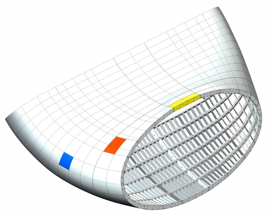
A rendering of a draft tube formwork shows the contours and the unique dimensions of each of the steel block structures in it.
You need to set up a workcell line to start cutting pieces to make slightly pitched rectangular forms and make a …
What's that now? It’s not a circle after all. It’s more along the lines of an ellipse. It’s a circle that has been flattened, so the sides are curved gently and it has tight radii at its ends. An ellipse doesn’t have any sudden changes in the radius, which means the radius changes continually and gradually along the circumference.
This is baffling. What is this project supposed to look like when it’s finished?
The left half of the ellipse is a mirror image of the right half, but the top half is not a mirror image of the bottom half; moreover, after making this ellipse, you have to make another ellipse, one that is a little different from the first, and join them. And then you have to make and join another and another, until you have made 22 in all. Is this a tube? Yes, it’s a tube. It’s a tube that will be assembled bit by bit. Imagine slicing a tube into 22 rings. You’re going to reverse that process, building one ring at a time and joining them.
You’re going to need a lot of steel, a lot of welding wire, and a lot of time. Oh, and you’re going to have to fixture all of the individual components that have irregular shapes and inconsistent sizes.
Designing a Draft Tube Formwork
Mankind has been building dams to control rivers for millennia; adding a hydroelectric generator to a dam is a bit of genius. The capital investment is vast and the maintenance cost is nothing to sneeze at, but it uses natural energy to make artificial energy. As long as rain is consistent and gravity doesn’t give out, it’s an excellent way to provide a steady stream of electrical current.
Designed and built to evacuate water from beneath a hydroelectric generator, a draft tube works as a sleeve to protect the dam. The dam is made from common concrete. It’s a good material for building a reservoir to contain water, but it’s not good for channeling water because it erodes too quickly. The draft tube is made from a specialized concrete that resists erosion even when exposed continuously to rushing water.
After the water leaves the reservoir and enters the hydroelectric unit’s inlet, it circulates around the rotor, pushing the vanes that rotate the turbine, thereby expending most of its energy. At this point the water drops into the draft tube. Constructed with curves and contours, the draft tube guides water vertically away from the turbine, then changes direction and widens so the water slows down and exits the dam horizontally to rejoin the flow of the river below the dam.
Engineering firm Wenlock Ltd., Shrewsbury, U.K., was contracted to develop a process for building a series of draft tubes for the Grand Ethiopian Renaissance Dam. Ethiopia is a large nation, home to more than 100 million citizens. When the dam is finished, the hydroelectric generators will develop 16,000 gigawatt-hours of power annually, which will help to relieve the country’s acute energy shortage.
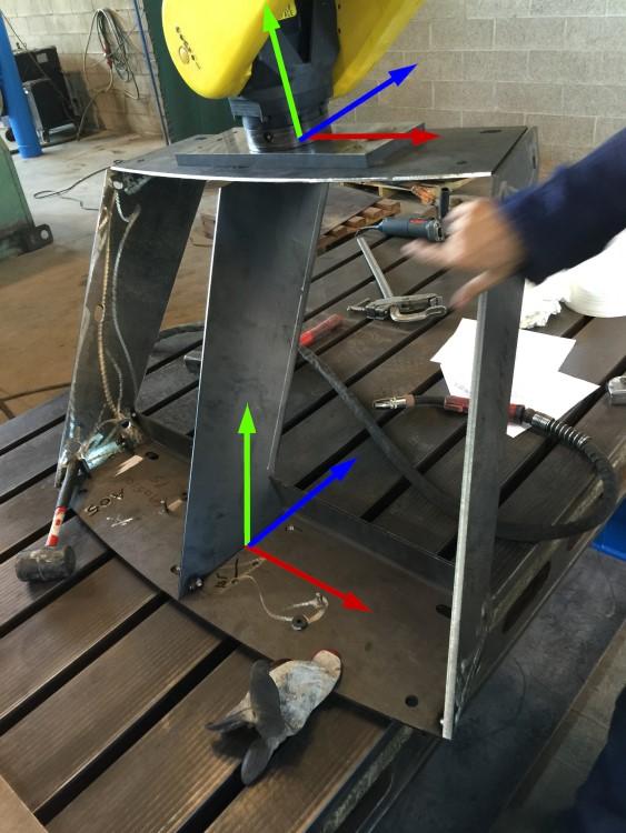
On the components of the draft tube formwork, the X, Y, and Z planes varied substantially.
It’s hard to grasp the sheer scope of the project. As a point of reference, the dam is so large that the reservoir behind it likely will take from five to 15 years to fill. The dam is big, the generators are big, and the draft tubes are big.
One more thing: The dam-builder didn’t put all its eggs in one basket. It contracted generators from two vendors. Each has its own designs for the generators, the water inlets, and, of course, the draft tubes. The fabricator that bids on this job will have to make draft tubes of two designs.
The Draft Tube Form Engineering Challenge
Fixturing a project with thousands upon thousands of unique parts is out of the question. If the fabricator were to build fixtures for this project, the time and effort for the fixtures would rival that needed to make the draft tube forms themselves.
The project came to the attention of Roberto Garziera, founder of Wenlock Ltd. Garziera draws extensively from his lengthy fabrication and design experience. His first job, one he worked every summer many years ago, was doing fabrication work for his father’s business. Exposure to machines and tooling at an early age provided keen insights about using metal fabrication processes to make components and assemblies. Adept at drafting with pencil and paper, he later embraced advanced 3D drafting technology.
His career has included designing industrial machinery, developing fabrication processes for components and assemblies for steel construction and infrastructure projects, and developing products and then designing the machinery and tooling needed to make those products.
“I understand design,” he said. Like many people in manufacturing, he has seen his share of OEM customers who understand ease of manufacturing and those who don’t. The reality of draft tube formwork is that it can’t be designed for ease of manufacturing.
“The main difficulty was modeling more than 500 unique blocks with external surfaces that were irregular to coincide with the draft tube shape while their internal surfaces were regular enough for bolting the blocks together,” Garziera said. “The construction also had to allow the dam-builder to apply props, install hatch doors for pouring the concrete and performing inspections, applying antifloating anchors, and allowing dismantling.”
So this is how it looked in detail: Make approximately 5,400 individual components and use them to assemble 528 box structures, then assemble those box structures into 22 rings of 24 box structures each, thereby completing one draft tube formwork.
“On every block, no two components were to be parallel or perpendicular to each other,” Garziera said. “After positioning one component—let’s start with the bottom plate—on the assembly table, it would be impossible to determine the exact location and orientation of any other component using common shop tools such as a ruler, square, or protractor.”
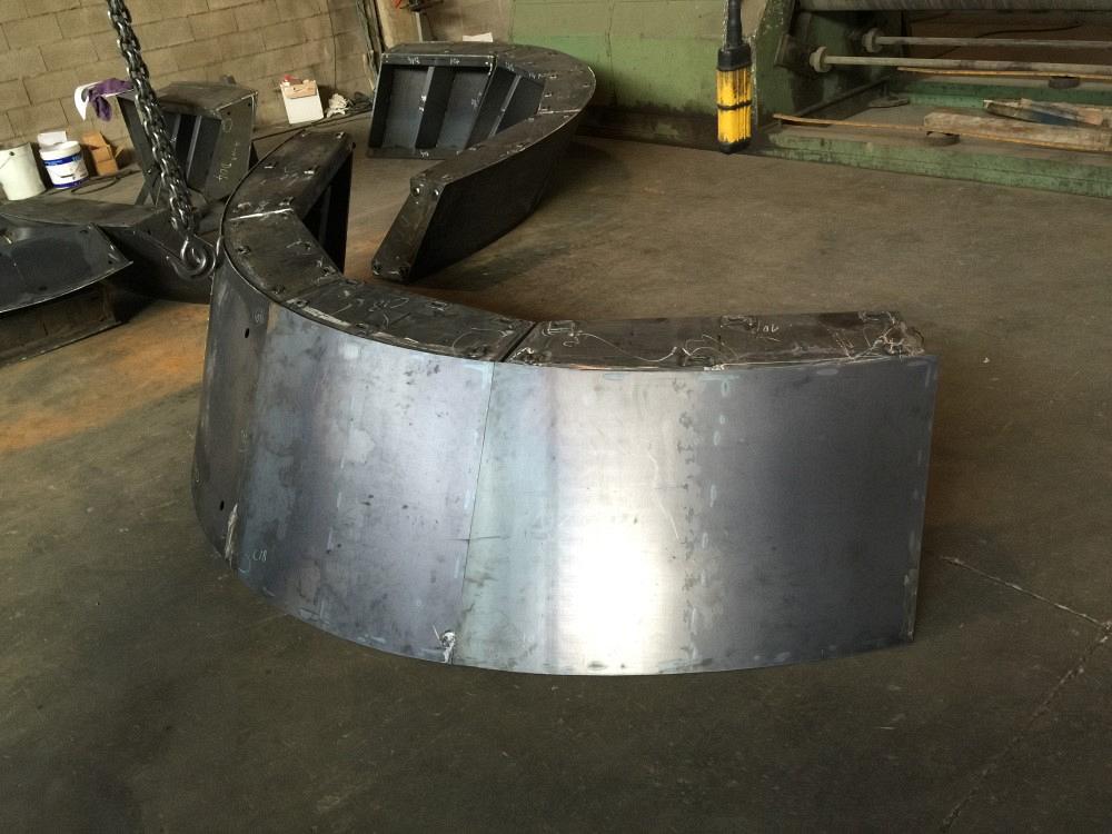
An ellipse takes shape. Every component had to be accurate so every box structure and every ellipse would be accurate and all of the ellipses could be joined together to make one vast assembly.
For the workholding aspect, Garziera would need something versatile.
Everyone knows that metal fabrication equipment becomes more versatile with each passing year. Three or four decades ago, most machines performed one function, but the equipment designers have been combining machine functions for a long time. A single machine cuts and punches, forms and shears, cuts and threads, and so on. At the same time, advanced control systems and programmability have made machines extremely versatile, especially toolless machines like laser cutters and waterjets.
For workholding, such versatility is likewise available. It comes in the form of a robot. Equipped with fully articulated joints and augmented with the unlimited versatility of a modern control system, a robot can be the ultimate fabricator or fabrication assistant.
For this project, using a robot to position each component for tack welding and then setting the assembly aside for manual welding in a later stage would be a possibility. That said, a successful implementation would require an unconventional use of a robot.
Certainly, the earliest robots were programmed, but those days are long gone. In the modern era, robots are taught rather than programmed. After setting up a sample workpiece in a workholder or jig, the operator moves the robot’s arm manually to its initial location, then to the next location, then the next, until the arm has traced out the path. After this is done, the robot knows all of the start and stop points for each step, whether it’s welding, cutting, deburring, or some other process. Another possibility is to manipulate the robotic arm by use of a joystick controller, but in the end, it’s about the same as manually guiding the robot’s arm.
In most circumstances, either of these is preferable to writing line after line of code to program the initial and final locations of each motion, the speed of each motion, instructions for turning the torch on and off, and so forth. However, making thousands upon thousands of unique parts, and getting them into position for welding, is not a case of “most circumstances.” For this project, using the conventional methods for teaching a robot to start at point A and move to point B would require tracing the cutting paths between 260,000 of point A and 260,000 of point B. Needless to say, this was out of the question.
Could Garziera work out some other way to use the robot?
Rediscovering CNC During the Draft Tube Formwork
Although the word manufacturing implies a manual process, the modern concept uses automation, assembly lines, and consistency for efficient production, specializing in a low mix (preferably, zero mix) and high volume. The wordMaking a draft tube form is an extreme case of high mix and low volume. Of the 5,400 individual components for this project, only a few were repeats. The fabricator would have to deal with every component as though it were unique, meaning this project had no mix.
Accuracy was another factor. Considering that any error in accuracy likely would be compounded across all 5,400 parts, it’s difficult to conceive that the beginning and end of each ellipse would meet if the box structure dimensions weren’t dead-on.
Without a viable strategy to make every part to the necessary accuracy, and precisely position for assembly each of the 5,400 unique, irregular parts with a jig, clamp, vise, or fixture, the subcontractor would run the risk of making a vast pile of scrap.
Garziera understood that the mode by which a robot learns a path is irrelevant. An operator can guide the robot’s arm along the path or use a controller to manipulate it, or a programmer can enter each command line by line, but in any case, the input is data that the robot’s controller turns into commands that it stores and uses.
Because Garziera had digital drawings of the draft tube formwork, he had enough information about each individual component’s dimensions, location, and orientation to export linear transformation data to create the necessary commands to program the robot. It was more than just a possibility; it seemed to be the only practical way to execute this project.
“We found a fabricator that had the capacity for this project, and we even found a used robot for the fabricator to use,” Garziera said.
In the end, Garziera devised a three-part strategy to make every part right on the money.
First, the fabricator would laser-cut every piece of steel for each box from a single piece of raw material so the thickness wouldn’t vary. Some parts needed a bend, so those were bent accordingly.
Second, each piece would be picked up and placed by the robot onto a stable work surface, the cast iron table of a large milling machine. To get the location just right, the robotic arm would move each piece to the destination, then execute a fully articulated 3-axis motion—roll, pitch, and yaw—for a proper and consistent placement. After tack welding (by workers, not the robot) at the fixture location, the assembly would be set aside for traditional manual welding. See it in action.
Finally, the robot would be programmed with another set of coordinates for final trimming with a plasma torch. This was done to finalize each part’s dimensions, helping to ensure the tightest possible fit-up between mating edges before assembling the boxes to form the ellipse sections.
Once the process was up and running, it ran smoothly and required no rework, according to Garziera.
Success in a project such as this one is based on, and shows off, the capabilities of CNC machines and robots. After programming, setup, and some fine-tuning, the machines run flawlessly. The full scope of this project comprised two pairs of formworks for the two types of draft tube comprising more than 20,000 unique components assembled to form more than 2,000 blocks to make four draft tube formworks.
This project undoubtedly sets a milestone in advanced techniques for precision metal fabrication. Garziera’s only disappointment is the orthogonal nature of nearly everything else in manufacturing and construction, which means this sort of solution isn’t likely to be needed again anytime soon.
About the Author

About the Publication
subscribe now

The Fabricator is North America's leading magazine for the metal forming and fabricating industry. The magazine delivers the news, technical articles, and case histories that enable fabricators to do their jobs more efficiently. The Fabricator has served the industry since 1970.
start your free subscription- Stay connected from anywhere

Easily access valuable industry resources now with full access to the digital edition of The Fabricator.

Easily access valuable industry resources now with full access to the digital edition of The Welder.

Easily access valuable industry resources now with full access to the digital edition of The Tube and Pipe Journal.

Easily access valuable industry resources now with full access to the digital edition of The Fabricator en Español.
- Podcasting

In this episode of The Fabricator Podcast, Caleb Chamberlain, co-founder and CEO of OSH Cut, discusses his company’s...
- Trending Articles
1
Tips for creating sheet metal tubes with perforations

2
Are two heads better than one in fiber laser cutting?

3
Supporting the metal fabricating industry through FMA

4
JM Steel triples capacity for solar energy projects at Pennsylvania facility

5
Omco Solar opens second Alabama manufacturing facility
