


Welding automation gets heavy
Accounting for process variation is key
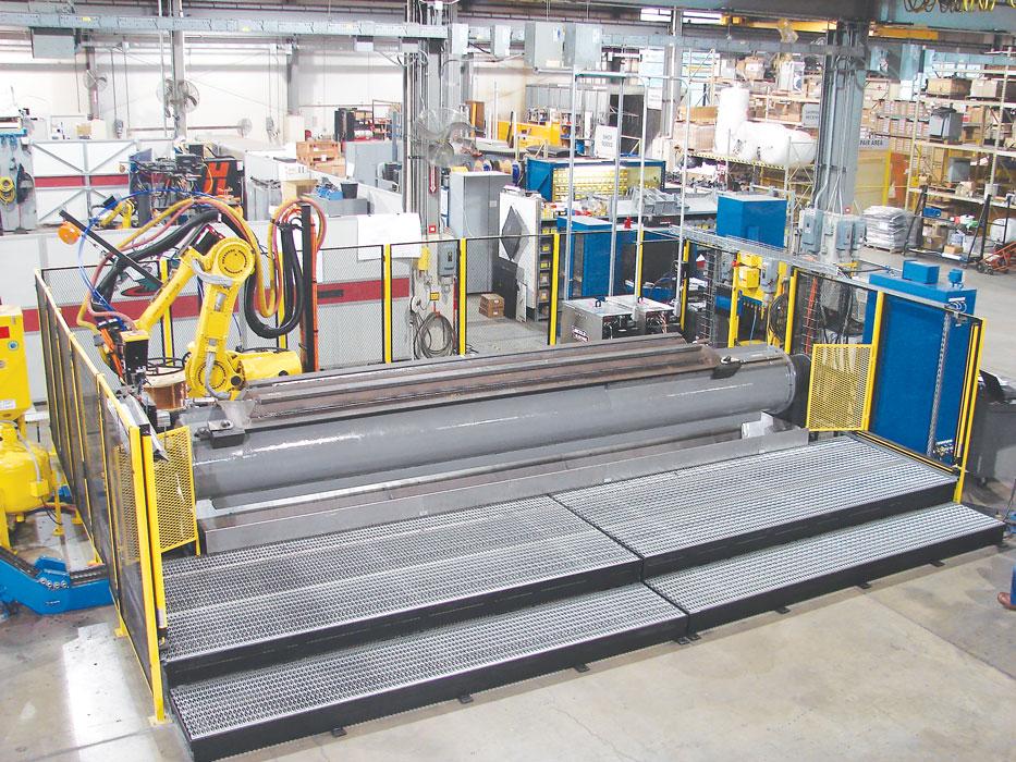
A single-axis head- and tailstock positioner is used in a submerged arc welding cell.
Automation for heavy welding requires careful consideration. The more information gathering, analysis, and planning that can be done upfront, the better chance the effort will lead to success. How will the positioning of the part affect the weld? How much variation will heat distortion cause? What is the right process for this part? How were the primary parts processed previously, and what variation will they present for welding automation?
Heavy-duty robotic welding applications encounter unique challenges. Robots, welding power supplies and waveforms, and welding wire must work together to achieve the high deposition rates these applications usually demand. Cycle times range anywhere from a few minutes to 40 hours, and increasing throughput to shorten that time is key for improving productivity.
Implementing heavy-duty welding automation entails a plethora of variables: weld process selection, positioning, weld distortion, and more. The goal is to minimize variation. This doesn’t mean a cell can’t be designed to handle a variety of parts. But every time a specific part is presented to the robot, it has to be handled in a consistent, repeatable way.
Positioning in Welding Automation
Consider how the part will be positioned during the weld cycle. Choosing the correct positioner often can simplify an otherwise challenging task.
A single-axis positioner usually rotates the part, such as with a turntable or headstock/tailstock (trunnion) positioner. A dual-axis positioner introduces another axis of motion, such as a rotation around the vertical axis of the workpiece.
Single- and multiple-axis positioners come in various forms. A tilt/rotate positioner is a dual-axis system that rotates the part 90 degrees, from horizontal to vertical (the tilt axis), while a turntable rotates the part around its vertical axis.
A skyhook positioner entails an L-shaped support that rotates around the horizontal axis while holding a turntable (or platter) that rotates the part around its vertical axis. These also come in a dual-station variety, with a rotating central base and a table on either side. This allows the operator to unload and load parts during the welding cycle.
A drop-center positioner is a U-shaped trunnion that, as the name suggests, drops in the center (creating the bottom of the U shape). While its shape does provide extra clearance and stability for welding large or long workpieces, the table attaches to both a headstock and tailstock, which, depending on the part, can prevent the robot from accessing certain welds.
Finding the right positioner starts with asking the right questions. How many robots will be involved in welding? How heavy is the part? Does the part need to rotate during the weld? The optimal position (1F) uses gravity to help the robot lay the weld. In this case, the robot program needs to accommodate any distortion that may be caused by the effect of gravity on the weld pool.
The Role of Simulation in Welding Automation
Modern 2-D and 3-D simulation tools help prove out the automation concept, design, and process, as well as help minimize risk. These tools help engineers understand what the optimal part position is as well as how many degrees of freedom are allowed. It also allows them to understand and correct for any robot reach issues, robot size requirements, weld torch configurations, weld access requirements, fixture clearances, and other variables.

Software simulation, including virtual reality tools, allows engineers to “see” the automated welding process in action before any part of the system is built or integrated.
Engineers simulating an automated system are no longer limited to the computer screen. Virtual reality tools offer engineers immersive visualization. This can improve internal design processes, enhance collaboration, and expedite ergonomic testing. Engineers can dive deep into automation concepts, ask better questions, and optimize the product and process before system design begins.
Managing Heat Input During Heavy Welds
Heat control can be a challenge in heavy-duty welding. How much heat input will occur during welding, and how much will the part distort because of that heat input? Could the use of modern welding technology, such as pulse welding, reduce heat input and, hence, reduce distortion? Engineers must understand how to eliminate as much distortion as possible through proper workholding and weld process optimization.
Weld distortion is caused by the expansion and contraction of the two metal pieces during the welding process’s heating and cooling cycles. Many factors affect the change in metal size. Understanding how and why distortion occurs will help minimize variation in the part, ultimately leading to a cleaner weld.
Performing weld distortion analysis upfront can help. Analysis allows engineers to use finite element analysis (FEA) software to simulate part distortion due to heat input. The FEA software allows engineers to enter material properties, process sequences, and part constraints in order to understand the effects of the weld process. Controlling weld distortion may lower material thickness requirements, because less distortion typically requires less postweld machining.
The order of constraint—that is, the order in which workpieces are clamped—can affect overall weld distortion significantly. Fine-tuning clamping sequences and fixture robustness can reduce postweld process requirements.
Product and process variation can interact to create weld gaps much larger or smaller than anticipated. Joint locations can move significantly during welding, often causing weld parameters to fluctuate. In these cases, variation simulation analysis can help engineers understand how the part, fixture, and weld process interact.
Engineers can run thousands of simulations in a few minutes. The simulation includes component CAD data as well as the production fixture’s principal locating feature. It allows engineers to review datum schemes in fixturing, component tolerances, and overall process robustness—all in a digital environment. Such “digital prototyping” should happen during product development and design, and before process development.
Looking Upstream
A robot cell needs to be made with the right materials, sensors, wiring, and shields, and the goal that drives these decisions is the control of variation. Simulations help engineers uncover the effects of variation, such as slight geometry changes from part to part. But this doesn’t mean that robotic welding isn’t practical or cost-effective, even for the heaviest parts.
The goal is straightforward: The robot needs the joint to be in the same spot every time. Engineers should look upstream to reduce variation in the work entering the welding cell. The part could be changed slightly so the joint is presented to the robot consistently.
Workholding also can help. In fact, with the right design, workholding can help to greatly minimize the effects of part-to-part variation. A good tooling concept will control how the part is presented to the robot.
Heavy Welding Tracking and Adaptive Fill
Sometimes, even after the part and workholding design is optimized, the joint geometry or location still isn’t consistent enough for reliable robotic welding. This is where through-arc seam tracking (TAST) can help. TAST makes real-time corrections to the weld path. Reading feedback from the welding current, TAST allows the system to adjust the robot path program in real time. Specifically, the software adjusts the robot’s vertical and lateral path to compensate for part warping or misplacement.
Another tool often used for heavy welding applications is laser guide tracking, or laser seam tracking. Here, a robot-mounted laser provides 3-D information about the joint by pointing just ahead of where the weld is being deposited. As with TAST, laser guide tracking allows the robot to adjust its path in real time. But unlike TAST, it also can trigger adjustments to voltage, wire feed, and travel speed based on changes in the bead formation.
Upfront simulation is essential for laser seam tracking success. Putting a laser on the end of the robot arm can cause access problems for joints in tight areas. Robot programs need to ensure the welding gun can access small areas, around tooling clamps, and along curves.
In these cases, a reach analysis simulation will help determine if the robot will be able to function properly. If a robot mounted with a laser can’t access a joint, it can replace its welding gun with a tracking laser using a tool changer. The laser tracks the joint and then returns to the home position, where the tool changer removes the laser and adds the welding gun. Unfortunately, this eliminates the real-time advantage gained from laser seam tracking. Regardless, the laser can improve welding accuracy, quality, and overall throughput, despite the added tool change.
Joint tracking works in conjunction with a welding technology known as adaptive fill. This allows the robot to adapt to changes in the required volume of the weld caused by part variation, tack welds, and distortion during welding.
Using information from machine vision, adaptive fill software measures the joint dimensions and volume, then determines changes needed in the welding parameters, such as the wire feed speed, arc voltage, and travel speed. This adjusts the weld deposition rate all while maintaining weld stability and density.
Wire and Welding Method
The two most common welding methods in heavy-duty applications are gas metal arc welding (GMAW) and submerged arc welding (SAW). GMAW uses a wire electrode that is fed out of the welding gun and protected from the atmosphere with a shielding gas that surrounds the arc.
With SAW, an arc forms between a continuously fed electrode and the workpiece. A blanket of powdered flux, which provides a protective shield and a slag, protects the weld zone. A shielding gas is not required.
While each has its advantages, SAW has better deposition, resulting in a continuous weld without any breaks. However, SAW draws more power and requires more equipment than GMAW. The part’s position is critical. Because SAW puts down more wire, the robot must remain in a consistent position to allow for straight linear welds or circumferential seam welds.
Welding power supply and wire manufacturers continue to optimize their systems for heavy welding. Some systems use high-deposition tandem wire and even metal-core wire. Although metal-core wire costs more, it can allow manufacturers to put down more wire faster with less rework.
Minimizing Variation in Automated Welding
Product and process variation is a reality in manufacturing, and the design of any automated welding cell, heavy-duty or otherwise, must account for and minimize that variation whenever possible.
Digital design and manufacturing technologies have advanced in the last few years. Welding power supplies have improved, as have the robots themselves. The right product design choices and well-designed fixtures can help enhance process effectiveness. Adaptive fill, seam tracking, and other technologies like touch sensing—in which the end of the welding gun is used as a touch probe to verify the joint location—help manage variation that cannot be designed out of the product or process.
Implementing well-thought-out automation boils down to two steps. First, design out all the variation you can. Second, use available tools to account for the variation that remains. To accomplish this, engineers now have more tools available than ever before.
Images courtesy of Genesis Systems Group.
About the Publication

subscribe now

The Fabricator is North America's leading magazine for the metal forming and fabricating industry. The magazine delivers the news, technical articles, and case histories that enable fabricators to do their jobs more efficiently. The Fabricator has served the industry since 1970.
start your free subscription- Stay connected from anywhere

Easily access valuable industry resources now with full access to the digital edition of The Fabricator.

Easily access valuable industry resources now with full access to the digital edition of The Welder.

Easily access valuable industry resources now with full access to the digital edition of The Tube and Pipe Journal.

Easily access valuable industry resources now with full access to the digital edition of The Fabricator en Español.
- Podcasting

In this episode of The Fabricator Podcast, Caleb Chamberlain, co-founder and CEO of OSH Cut, discusses his company’s...
- Trending Articles
1
Tips for creating sheet metal tubes with perforations

2
JM Steel triples capacity for solar energy projects at Pennsylvania facility

3
Are two heads better than one in fiber laser cutting?

4
Supporting the metal fabricating industry through FMA

5
Omco Solar opens second Alabama manufacturing facility
