


Senior Editor
What happens to a metal fabrication shop when experienced skilled workers leave a forming department? If the process isn’t under control, chaos can reign. Wila
During his early days working in a fabricator’s forming department, Larry Boden arrived home one evening and showed his wife a set of calipers. To her surprise and amusement, he proceeded to measure the width of her hair, then went on to describe how small changes in sheet metal thickness, even the chemical makeup, could affect how it bends on a press brake. The precision of it all fascinated him.
“I told her, ‘Isn’t that something?’ From that point on, I was hooked.”
Boden went on to perfect his bending craft, developing processes so that even the most complicated parts could be bent with one staged setup, without the benefit of common-shut-height tools or offline simulation software. Now a press brake tooling specialist at Mate Precision Technologies, Boden said he believes that fascination is what’s missing from too many forming departments today. To spark the fascination requires knowledge that, with the retiring boomer generation, is all too quickly vacating the industry.
“People are investing in technology out of necessity,” Boden said. “They need it to stay competitive. But technology is not the complete answer. You need someone who has a passion for bending, someone who wants to understand it, who’s hungry for knowledge; someone who can answer those questions of ‘why’—why sheet metal bends the way it does.”
Many bending departments out there need a major refresh. To find out what that entails, The Fabricator reached out to experts at three major tooling suppliers: Mate, Wilson Tool International, and Wila. The specific revitalization process will depend on the operation, but most will involve at least three key steps: (1) know the fundamentals, (2) police the process, then (3) start to visualize it.
Assuming operators are air forming (and most are these days), they need to know that, when bending most materials, it’s the die width, not the punch tip, that forms the inside bend radius. The depth of penetration of the punch into the die (overbending for springback) determines the bend angle (see Figure 1). The basics are worth clarifying, especially since the most experienced industry veterans today likely began their press brake career bottom bending, a method where the punch radius does indeed form the inside bend radius.
Air bending is a different animal. The wider the die opening, the greater the inside bend radius. A piece of 60-KSI tensile strength carbon steel might be predicted to form at about 16% of an appropriately selected die opening (like one that’s eight times the material thickness). The operator checks to ensure this material grade at that thickness and that bend length can be formed safely, considering the tonnage limits of the tooling, press brake, and placement of a toolset across the brake bed. The narrower the die, the more forming tonnage a job will require. Over-tonnage a brake, and you can cause ram upset, or the permanent bowing of the brake bed. Say goodbye to bending accuracy and repeatability.
Material tolerances vary, both with thickness and hardness. On new material, an operator should perform test bends and measure the resulting radius to establish a forming baseline for this material grade and thickness from that supplier.
“Get this data right when that material is available, before an operator is charged with running a job and getting parts out the door,” said David Bishop, technical sales engineer and training manager at Wila. “As accurate as today’s press brakes and precision tooling are, in many cases, the quality of the material is actually getting worse.”
Material and tooling suppliers detail the minimum recommended inside bend radius for various grades and thicknesses to avoid part cracking, usually expressed as some multiple of the material thickness.
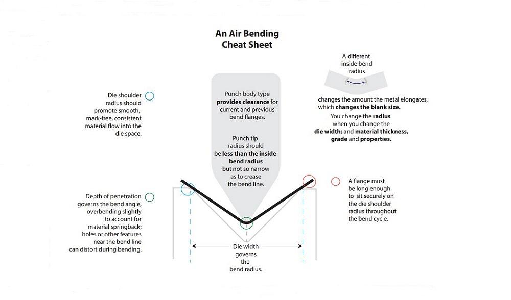
FIGURE 1. Air bending is not bottom bending, a fact worth clarifying even today—especially since many of the most experienced operators began their careers with bottom bending.
“I still have operators tell me, ‘I get orders for parts all the time that tell me to do something like putting a 0.031-in. bend radius on a piece of 1/4-in. steel,’” Bishop said. “It’s like, ‘If it can be drawn on a CAD system, you should be able to form it on a press brake.’ Obviously, that’s not going to happen.”
“This is why we have the air bend force chart,” said Steve Brown, bending product manager at Wilson Tool. “It’s the chart that details the inside radius, minimum flange length, the tonnage you’ll produce, and how it all changes with different material thicknesses and material types. So many operators now just gloss over it. With an automated process and offline programming, they just do what they’re told. But if it were me, I’d want at least a basic understanding, because if the person who generated the program made a mistake or lacked knowledge, I’m the one getting paid for production.”
How much the bend elongates the material depends on the radius formed, which again, in an air form, depends on the die width. Change the die, you change the radius, which changes the amount of elongation, which changes the overall blank dimension. That chain of events is why excellence in forming takes a village, both in front of the press brake and in the design and engineering departments. A true bending department refresh can’t happen in a vacuum.
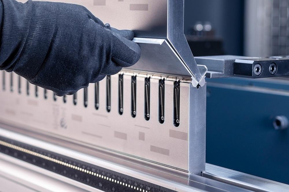
Ideally, fabricators shouldn’t quote or design parts without a few bending fundamentals in mind. These include the open height (see Figure 2), stroke length, maximum bending length, and tonnage capacity of the press brakes on the floor.
“If you’ve got a 7-in.-deep box to form, but the brake has only 14 in. of open height, operators won’t be able to use tooling that is tall enough to get inside the box, and even if they were able to do so, they would never be able to get the part off the tooling,” Bishop said, “no matter what tooling they have.”
Parts will be affected by the grain orientation, too. As Bishop explained, “While it is tempting to always maximize the number of parts cut from a sheet, as much as possible, it is always a good idea to cut all of the parts with the grain running in the same direction. And it is always preferable to have as many bends as possible run perpendicular to the grain in the material.”
Every change in bending can have a domino effect of unintended consequences. For example, Bishop described a situation in which a customer’s part had a design change that required a shorter flange. The operators simply altered the program at the brake to account for it—no problem, right? They soon realized that, of course, the die width needed to change to accommodate that shorter flange. So, they changed the die opening. “Of course, when you change the die from the larger opening to the smaller opening, your bend radius and blank size will often change.”
Challenges like this create increasing levels of frustration. Operators in a rush might start choosing their own tooling without telling anyone. Different people on different shifts use different toolsets. At the press brake control, they alter or create different programs for the same part. Scrap increases and productivity suffers.
Brown recalled one shop where a forming department kept sending parts to quality assurance, which promptly rejected them. “So they put the part through again, and it was rejected again. And again. And again. There was nothing in their process to enable the operator to make it right the second time.”
As sources explained, good operators often want to do the right thing, but they’re frequently pressured to just make it work and get parts out the door. If formability discussions were to occur before a job hits the floor—during engineering, quoting, or the design phase—good operators wouldn’t be put between a rock and a hard place nearly as often.
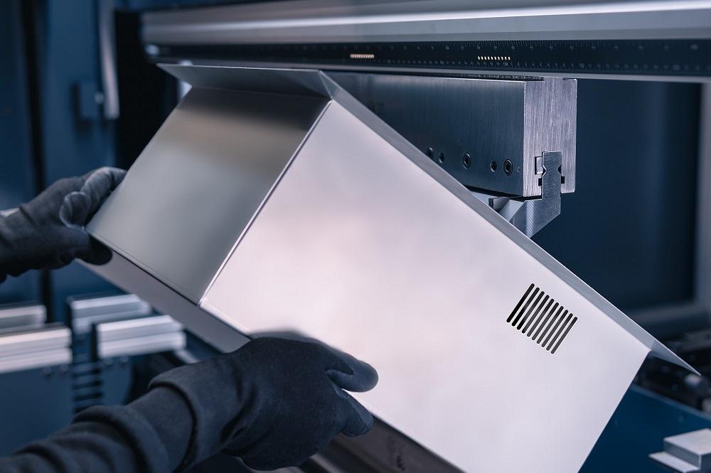
FIGURE 2. Box bending requires that brakes have a certain open height. Otherwise, the tools won’t be able to open enough to remove the fully formed box from the tooling. Wila
“I call it ‘policing the process, all the way through the shop,’” Bishop said, adding that if a fabricator has lost control of the process, new tooling or bending technology likely won’t solve the problem.
When operators and engineers collaborate and know the basics, they can more easily visualize their parts being formed before taking them to the press brake. It’s a nuanced process, and the more operators understand it, the better they will be.
One Punch, Many Bends. In air bending, the punch accomplishes two things. First, it’s a pushing mechanism to drive the material into the die opening. Again, the radius forms as a percentage of the die opening. The punch radius has no effect on the inside bend radius on most materials. Exceptions exist, like when bending soft 5052-H32 aluminum, but for the most part, operators aren’t choosing a punch to achieve a certain radius.
Second, the punch geometry should provide as much bending freedom as possible, providing necessary clearance so parts form properly and are manipulated easily between bends. Both attributes maximize versatility and minimize tool changes.
As long as the punch radius is less than the natural inside bend radius that forms as a percentage of the die opening, and the punch tip is not so sharp that it digs into the material, one punch can be used to bend a wide variety of bend radii, angles, and part configurations (see Figure 3).
“Because of the advancements in tool design, bending software, and machine accuracy, it is now possible to reduce the amount of tooling that is required to bend a wide range of materials,” Bishop said. “This will result in using the least amount of tooling to do the most work while minimizing the number of tool changes.”
He cautioned, of course, that any change in tooling needs to be made in collaboration with design and engineering, based on sound bending fundamentals, lest those unintended consequences rear their ugly heads again.
Box Bending. When performing a deep box bend, Boden recalled relying on specific tricks to get those corners to line up just right, including “shimming” with a piece of paper on the portion of the die shoulders just below where those final two corners form up.
To understand why this works again calls for a little process visualization. The paper makes the die ever-so-slightly taller at either end of the bend. This overcomes the natural resistance when forming those final corners and, dialed in just right, can create a near-perfect corner that welders will love.
“Again, this really requires that operators understand the ‘why’ behind air bending,” Boden said. “If you don’t understand the ‘why,’ it’s difficult to come up with a solution.”
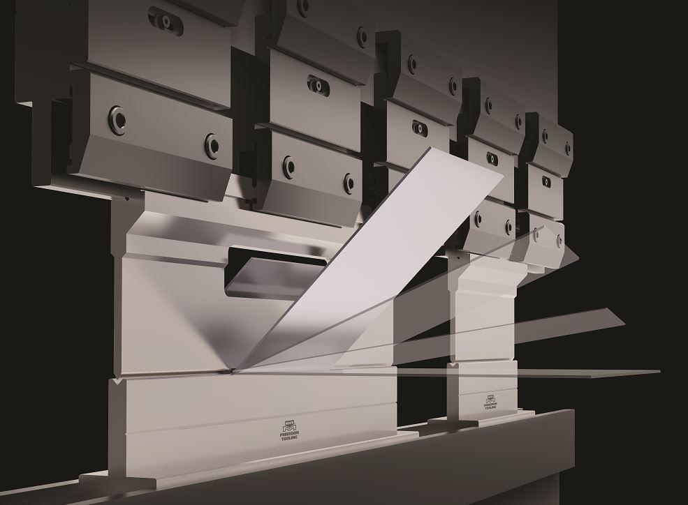
FIGURE 3. One punch can form a variety of bends. Different punch bodies and punch angles give clearance for current and previously formed flanges. Here, a window punch provides clearance for a deep return flange. Mate Precision Technologies
Keeping with that visualization of box bending, operators can see the necessity for ears on the punch when forming boxes with return flanges on the top (see Figure 4). As Brown described, “To get inside a 4-in.-wide box [for the final bend], how long does that punch need to be? It can’t be 4 in. The tool has to be slightly less than 4 in., usually between two and four times the material thickness.” Why? The very end of the punch would collide with the previously formed radii on either side and perpendicular to that final bend. To the less experienced, it can be tough to see. But as operators spend more time in front of the brake, they start to think in three dimensions.
Sheet Marking. Urethane drape (tape) can help with marking issues. Still, tackling the root cause is often ideal. This can involve scrutinizing the material surface and cut edges on the blank. The cleaner they are, the better.
“If you have the experience and knowledge to know when you are going to have issues with sheet marking, you can almost always select the proper solution before bending the first part, instead of implementing a solution after the material has been sent to the press brake for production,” Bishop said. “This is true for most bending problems.”
The problem often arises when you use sharp die-shoulder radii, especially combined with small die openings. But even a V die of the appropriate width can cause marking if it isn’t stored or handled properly (see Figure 5). A damaged die shoulder can wreak havoc on surface-sensitive material—but is that die shoulder truly damaged?
“A damaged tool and a tool with galling start out looking nearly the same,” Brown said, adding that the fingernail test can help here. Scrape your fingernail along the die shoulder, and you might feel it fall into a nick or divot. “It’s often hard to tell if the divot is damage, or there is material buildup,” Brown said. “It all looks like damage, but your fingernail may have fallen off a ridge of buildup, and the cavity is actually the die surface.”
Galling—bits of metal caught from the sheet metal surface or dross from cut edges (especially for galvanized material and aluminum)—sit on the die shoulder surface and, if addressed regularly in the process, can be wiped away.
“Wait too long, and you let fragments continue to build and work-harden, and now the die looks like it’s damaged,” Brown said. “Clean-up will require more aggressive scraping. Still, scraping or using abrasive pads on precision tooling doesn’t go together well.”
Another solution might be to consider a less sharp die radius, “so instead of a grabbing action, you get more of a rub,” Brown said, adding that such small tweaks can slow gall formation, make bending more consistent, and prolong tool life.
Short Flanges, Features on Bend Lines. A job might require a small die-shoulder radius because of a short flange, which needs to “catch” the die shoulder to prevent it from being pushed into the die opening during bending. There are other methods of dealing with short flanges, though.
The same goes for features on or near bend lines like holes, which can distort when bent. Rotary dies (with rotating cams that support the material throughout bending) can overcome this issue (see Figure 6). So can urethane die inserts of the right durometer.
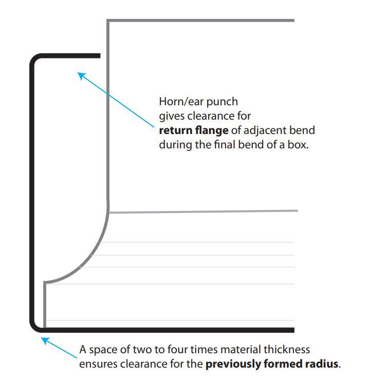
FIGURE 4. To avoid colliding with the previously formed radius, the punch length requires a little clearance to perform the final bend of a box—often one to two times the material thickness on each end, two to four times material thickness on the overall bend length. This would apply to sheet metal 12 ga. and thinner, assuming the V opening selected is creating a radius that’s one times the material thickness.
Still, knowing that short flange or hole on the bend line might be an issue from the get-go could spur a design change, which would make everyone’s life a lot easier. At the very least, the shop should have a strategy for working with challenging parts, know the possible costs behind taking those steps (like the need for additional tooling), and move forward with a plan—not just toss the job to the forming department and hope for the best.
In highly efficient fab shops, learning never stops and knowledge is always shared. But what if a brake department’s most experienced people get sick, retire, or suddenly leave the company? Even worse, what if setup sheets lack clarity, tool selection isn’t standardized, and, because of operational chaos, operators have been left to figure it out on their own?
“Invest in outside training,” Boden said, “real operator training. Find an expert, and quickly set up a fundamental training program to get some standardization. You don’t want everyone in the brake department doing something differently. When you get that, you get chaos.”
Bishop added, “I’ve become convinced that if sheet metal fabricators are going to assure themselves of having skilled machine operators and programmers, they are going to have to develop their own in-house training and developmental programs.”
Everyone in the industry is recognizing just how important fundamental training is. And outside training is available. The Fabricators and Manufacturers Association offers it, as do machine and tooling vendors. Such training should give people that spark to learn more, get creative, collaborate, and make the bending department—the beating heart of any fab shop—stronger than ever.


The Fabricator is North America's leading magazine for the metal forming and fabricating industry. The magazine delivers the news, technical articles, and case histories that enable fabricators to do their jobs more efficiently. The Fabricator has served the industry since 1970.
start your free subscription
Easily access valuable industry resources now with full access to the digital edition of The Fabricator.

Easily access valuable industry resources now with full access to the digital edition of The Welder.

Easily access valuable industry resources now with full access to the digital edition of The Tube and Pipe Journal.

Easily access valuable industry resources now with full access to the digital edition of The Fabricator en Español.
In this episode of The Fabricator Podcast, Caleb Chamberlain, co-founder and CEO of OSH Cut, discusses his company’s...


