


Contributing Writer
Images: WILA
Sheet metal forming on a press brake has its share of myths. Amid all the noise, it’s tough to know what’s true and what isn’t. With that in mind, here are six myths that can prevent fabricators from being as productive they can be.
This is not always true. A standard die can be ground away (relieved) on the back side to make it possible to create two opposing bends with a shorter distance between the bend centers. This provides clearance for the down-flange created with the first bend. It also makes it possible to form parts with acute bends, 90-degree bends, and offset bends in a single handling (see Figure 1).
The strategy does have some limiting factors. First, the back side of the die can be ground off only to the tangent point in which the shoulder radius on the V opening meets the flat surface on top of the die. Second, material will be consumed as it’s drawn into the die during forming. So, while it will not work for forming very small offsets, such as material-thickness offsets, it can often work well for forming medium to larger offsets.
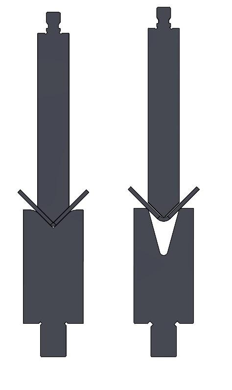
This was largely true with press brakes produced before the turn of the century, but for the most part, this is no longer the case. In the past, many press brake controls recognized when the punch tip’s included angle was larger than the die’s V opening. When that occurred, an alarm appeared, indicating a possible tooling collision, and prevented the ram from advancing and driving the punch into the die.
Times have changed. Today, matching the punch tip and die angle is no longer necessary (see Figure 2). Doing so only limits the versatility of the die. What is important is how far the punch tip can be driven past the tangent points on the die shoulder radii before a collision occurs.
The only limiting factor now is the angle of the punch tip. If it’s 86 degrees, trying to bend an included angle of less than 86 degrees would cause a collision. Of course, the same is true with any punch tip angle greater than the angle of the die’s V opening.
No longer needing to match the punch and die angle opens up a host of opportunities—especially regarding the use of acute-angle dies. For example, if you are air bending, and most bends you make are 90-degrees in 10-ga. and thinner mild steel, stainless steel, and aluminum, you can use punches with common 86-, 80-, and 75-degree tip angles to form these materials with 30-degree dies. If you should ever need to produce acute-angle bends on any or all of these materials, all you need to do is add an acute-angle punch. This eliminates the need for two sets of dies, potentially eliminates a lot of die changes, and will save you a lot of money.
Yes, a punch that is 4 in. (100 mm) tall is less expensive than a punch that is 6 in. (152.4 mm) or 8 in. (203.2 mm) tall. That will save you money in the short term. But if you are a contract sheet metal fabricator, you will likely contact your tooling supplier at a later date to purchase the same punch profile in a taller height to accommodate a part that your short punch is unable to form. The same is often true for companies that fabricate their own products.
When you buy a short punch and then buy a tall version of the same punch at a later date, you will have effectively purchased the same tool twice. And more than likely, you will have wasted a considerable amount of money.
Taller punches provide additional capacity when it comes to forming taller and deeper parts, especially four-sided parts such as boxes and parts with long return flanges like deep U-shaped channels (see Figure 3).
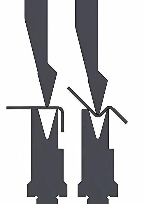
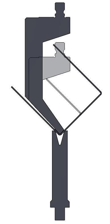
FIGURE 1. A standard die is relieved in the back to allow a shorter distance between bend centers and provide the necessary clearance for offset bends, without the need for a dedicated offset tool.
Of course, taller punches consume more open height. Generally speaking, I always recommend a minimum of 4 in. (100 mm) or more of working space between the punch and die to facilitate easy part manipulation during bending and part removal after bending. However, parts like deep boxes and U-shaped channels can require considerably more.
Die heights of approximately 2.165 in. (55 mm) are fairly versatile and cost considerably less than taller dies. If your press brake open height allows, you can always add taller dies, such as 4 in. (100 mm), when necessary. Be sure you have sufficient working space before purchasing taller dies.
If your press brake has a large amount of open height—say 23 in. (600 mm) or more—you will probably need to use taller punches and dies to bring them together at the bottom of the stroke. You also need to plan for the additional cost of these tools when purchasing your new press brake. Still, the versatility these press brakes offer—combined with punches 6 in. (152.4 mm), 8 in. (200 mm), or taller, and dies that are 4 in. (100 mm) and taller—is simply incredible.
This too is simply not true. Modern CNC press brakes take full advantage of air bending technology, and they’re incredibly fast, efficient, flexible, and productive. Nevertheless, bottom bending and coining still have their place.
Consider one manufacturer that wanted to revive a legacy product line they produced decades earlier. Those products were extremely successful, so the company wanted to replicate everything. The colors, material, and dimensions had to be exactly the same. This included a requirement for inside bend radii that were “as small as possible.”
I proposed air bending tooling with dies that would generate inside bend radii equal to the material thickness. I was shocked when I was told that they would be much too large. Because the products were manufactured many years ago, they were produced with tooling designed for coining. At the time, coining was the only way to get the accuracy and finished-part quality they required (see Figure 4).
As noted above, air bending provides a long list of benefits. Still, in some cases, for whatever reason, air bending simply will not work—like when the inside bend radii are smaller than the material thickness. I suggest that you take this into consideration when purchasing your next press brake. Also consider the customers you will be doing work for, and the types of customers that you would like to court in the future.
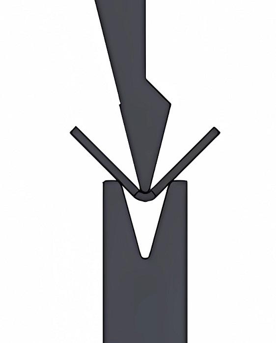
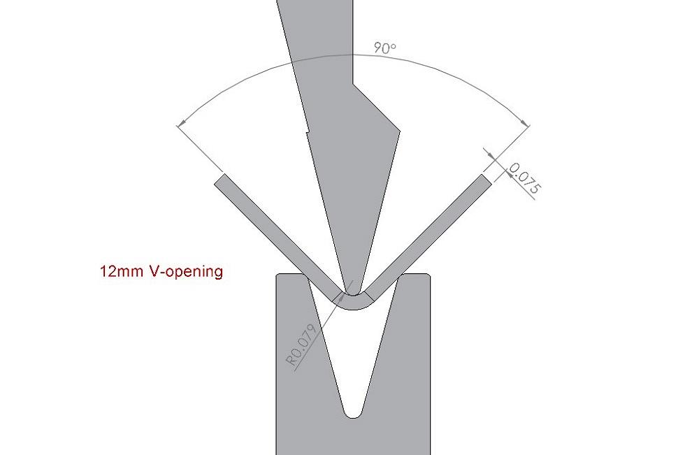
Well, yes you can, but it depends on how small of an inside bend radius you need (see Figure 5). When air bending mild steel and soft aluminum in gauge thicknesses, you can obtain inside bend radii very close to the material thickness by using a die with a V opening that’s equal to six times the material thickness.
For instance, if you bend 16-ga. mild steel in a 0.394-in. (10 mm) V opening, you will generate an inside bend radius of approximately 0.066 in. When bending 12-ga. mild steel in a V opening of 0.630 in., you will get an inside bend radius of approximately 0.105 in.
Air-bent inside bend radii of one material thickness look like fairly sharp radii to the naked eye. Companies with strict requirements for sharp inside bend radii will often accept them—especially if it eliminates the need for them to purchase tooling designed for coining, and if coining’s tonnage requirements push their press brakes to their limits.
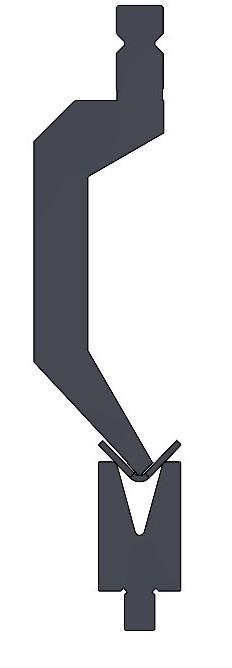
FIGURE 2. The illustration shows an 86-degree gooseneck punch and a 30-degree die. Matching the punch and die angles are no longer necessary. What is important is how far the punch tip can drive past the die shoulders.
While you can do this with mild steel and soft aluminum in gauge thicknesses, you will get the best results with 12 ga. and thinner. The distance between the material’s neutral axis and the outside bend radius increases as the material gets thicker; subsequently, the outside bend radius is subjected to additional stretching, thinning, and possible cracking.
Some fabricators successfully bend hot-rolled steel up to 0.188 in. (4.8 mm) thick using V openings of six times the material thickness. Of course, success when doing so relies on the material being of good quality and bending transverse to the grain whenever possible as opposed to parallel with it.
After spending five or six figures on a multi-axis CNC press brake, nobody wants to spend a penny more than necessary for tooling. Press brake owners attempt to get by with the fewest number of punches possible, which results in them having a very narrow range of punch tip radii. This can actually lead to higher tooling costs in the long term.
When punch tip radii are frequently subjected to excessive loads, they begin to break down at a much faster rate than normal. This effect will be exaggerated when bending abrasive materials like hot-rolled steel, perforated sheets, workpieces that weren’t properly deburred, and materials with a high yield strength such as stainless steel.
As punch tips break down, microcracking develops on the area of the punch tip that engages the material and will slowly spread over a wider area of the punch tip. Over time, the punch tip may also begin to develop flat spots. This can have a negative effect on your blank sizes, creating the need to replace the damaged punches.
The guidelines that I use for punch tip radius (PTR) selection, and have had very favorable results with, are as follows:
Select punches made of a high-quality alloy steel, precision-ground and hardened on the tip (see Figure 6), and keep the punch tip clean and free of rust and corrosion. It is equally important to use it within its proper load rating. Do all of this, and you can expect that punch to remain in new or like-new condition for 10 to 12 years, regardless of the number of parts you form with it.

The Fabricator is North America's leading magazine for the metal forming and fabricating industry. The magazine delivers the news, technical articles, and case histories that enable fabricators to do their jobs more efficiently. The Fabricator has served the industry since 1970.
start your free subscription
Easily access valuable industry resources now with full access to the digital edition of The Fabricator.

Easily access valuable industry resources now with full access to the digital edition of The Welder.

Easily access valuable industry resources now with full access to the digital edition of The Tube and Pipe Journal.

Easily access valuable industry resources now with full access to the digital edition of The Fabricator en Español.
In this episode of The Fabricator Podcast, Caleb Chamberlain, co-founder and CEO of OSH Cut, discusses his company’s...


