


Bending Product Manager
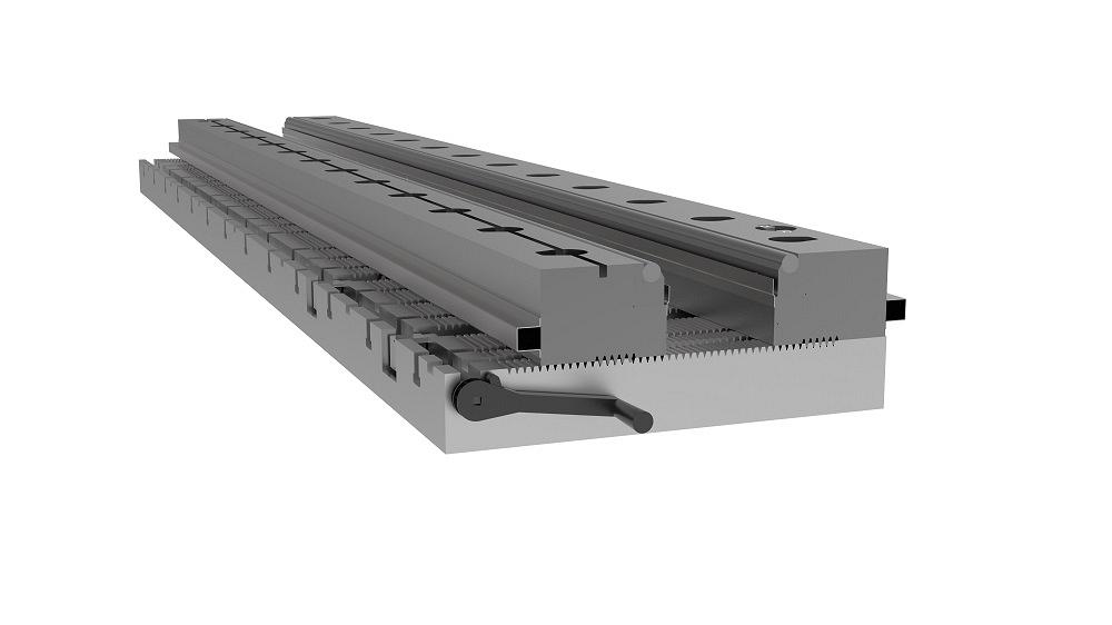
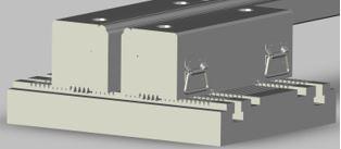
FIGURE 1. Adjustable V dies are designed to be left in the press brake and adjusted to create an opening that can accommodate heavy and thick materials, about 0.25-in. plate and thicker.
A lot of attention often is paid to handling heavy material at the press brake. What’s the most efficient way to get it into the brake? How can a crane or supports be used to bear the weight of the material during the bending process? What can be done to streamline the removal of the formed part and efficiently move on to the next similar workpiece?
But handling is not the only opportunity for process improvement. The tooling setup in the press brake can provide a real chance to minimize downtime when it comes to job changeover.
For a precision sheet metal shop that changes over tooling in a brake five or six times a day, the need to streamline that process is obvious. But does a heavy fab operation that changes out tooling in the brake once every couple of days require this type of critical examination? Actually, yes.
Changeout of a 10-ft.-long section of tooling, for example, is no small feat. It can’t be done by one person in many instances, which means that co-workers on the shop floor need to be gathered. Then it’s a tedious process to slide the tooling out, find its home, grab the replacement tooling, and slide that into place. Sometimes such changeovers can take hours.
Adjustable V dies and replaceable radius tips on punches can help to minimize the time between these typically time-consuming changeovers. It gets the press brake back in money-making mode much more quickly than relying on the good fortune of finding enough shop floor workers to manually make the change.
Adjustable V dies (see Figure 1) are exactly what the name suggests: They are flexible enough to create an opening to accommodate heavy and thick materials, about 0.25-in. plate and thicker. Usually the adjustable V dies are used in high-tonnage applications and for jobs where the workpiece length is measured in feet, not inches.
They are designed to accommodate various thicknesses; some of the openings can be as small as 2 in., and there also is the rare piece of tooling that can open to 24 in. The tooling can be made in smaller sections for easier handling by one operator, but in most cases, fabricators choose to have the adjustable V dies made in longer sections to match most of the work being done on the press brake.
Adjustable V dies comprise a foundation with a grooved surface and two side blocks (see Figure 2) that move along the grooves as the tooling is adjusted to create the V opening. Often a handle is used to move the side blocks in and out. Each side block has an insert holder on which a chrome rod sits. The chrome rod assists the bending action, alleviating some of the press tonnage that might be required to bend thick material if the workpiece is moving over the fixed shoulders of a traditional single V die.
This design approach is cost-effective for the metal fabricator because the chrome rod and the insert holders are the only items that bear the brunt of the bending process. The chrome rods are commodity items. The insert holders last longer than the rods, but replacement is infrequent. The side block bodies are designed for longtime usage and likely will not need to be replaced.
In some applications where the job entails bending something very hard, like high-strength steel or armor plating, the insert holder is upgraded. The entire insert holder is made of some sort of abrasion-resistant metal that can stand up to the aggressive bending action.
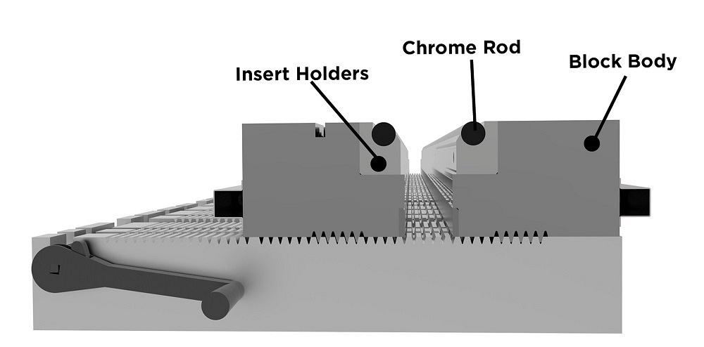
FIGURE 2. The insert holders and chrome rods are the parts of the adjustable V die that undergo the most wear and likely will need replacing. The block bodies have a longer life span.
When fabricators need to minimize marking, bend short flanges, or prevent distortion of nearby holes, inserts with paddles can be used (see Figure 3). The paddles start out flat, and when the ram enters the workpiece on top of the tooling, the material glides on the flat surface instead of grabbing the die’s shoulder radius. As the ram drives the punch down into the material, the paddles open up to a V shape, allowing for the full form to be made. The tooling helps to reduce the friction and concentrated load during the bending process.
These adjustable V dies come in some basic designs.
Manual Adjustments With Shims. This is the most basic design and the most inexpensive. Pins are loosened manually to free up the side blocks, and shims are used to place the blocks where they need to be. When done, the pins are tightened and bending can begin.
Manually adjusting this type of tooling with shims is a very time-consuming process. Typically, two people are required for the job, which can take two or three hours. This type of adjustable V die is considered a first-generation design and has been improved in newer die designs.
Just as there are options for the inserts for die shoulders, adjustment options on these flexible dies are available too. Basically, adjustment can take place manually or with full automation. As a rule, as automation is added, price goes up, and changeover time goes down. All of the following designs support one operator and no equipment changeover.
Manual Clamp and Handle Adjustment. With this type of adjustable V die, the bolt holes are on the top of the die blocks and an air wrench can be used to quickly loosen and tighten them (see Figure 4). When the bolts are loosened, a spring in the side block engages and lifts the side block above the grooved teeth. Each side block moves individually and easily on roller bearings. Using this option, changeover should be accomplished in 15 minutes.
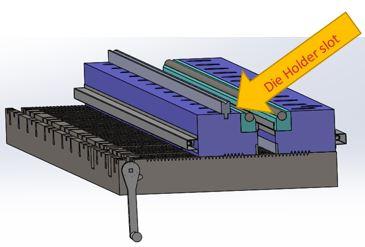
Manual Clamp and Ball Screw Adjustment. The introduction of a ball screw design allows for adjustment of both the front and back with the crank of a handle. This design also supports a die holder that can be added to the side block body so that smaller or other die types can be used without removing the adjustable V die (see Figure 5). With this setup, changeover can be accomplished in about 10 minutes.
Hydraulic Clamp and Manual Handle Adjustment. A simple hit of the button engages the hydraulic actuation that releases the side blocks from the grooved teeth. Each block moves individually by pulling or pushing a handle. A typical changeover can be made in four minutes with this arrangement.
Hydraulic Clamp and Ball Screw Adjustment. Hydraulic actuation releases and engages the side blocks with the button push. The side blocks are adjusted with the hand crank. It should take one person about four minutes to change over to the new tooling setup.
Hydraulic Clamp and Servo Adjustment. This setup works like the previous hydraulic clamping, except an electric servomotor moves the side blocks into place. No handles or cranks are present. Something this elaborate likely sits permanently in a press brake.
FIGURE 3. Inserts with paddles that move with the bending action of the plate help to reduce the friction and concentrated load during the bending process.
A conversation about minimizing downtime when bending thick materials wouldn’t be complete without a discussion about upper tooling as well. In heavy-duty applications, the punches can be just as heavy and unwieldy as the dies.
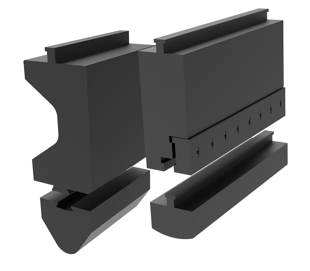
To remedy this, replaceable radius tip punches are useful. These tip inserts slide on and off the universal punch body. No adjustment is required between the punch radius changes.
Most replaceable radius tip punches are locked into the punch body with a clamp plate. Some, however, have a dovetail design and are loose enough for easy removal but have a tight enough fit to ensure consistent bending (see Figure 6). This is a common design when bending in the heavy material realm because die openings tend to be larger, materials tend to be inconsistent from one batch to another, and precision is defined a bit more loosely. If clamping the punch in place is desired, a design with a clamp plate can be created to secure the punch tip.
Different radius tip sizes are used depending on the material thickness being formed. The stems of these punches are actually fairly narrow (1.25 to 1.5 in.) but are usually made of very high-strength tool steel to withstand plenty of pressure.
While lighter than overall sections of upper tooling, the replaceable radius tips can be pretty heavy as well given their lengths. To help with this, these inserts can be built in sections so that one operator can handle tip insertion and removal, or fork holes can be integrated into the insert design so that a lift truck can be used.

The Fabricator is North America's leading magazine for the metal forming and fabricating industry. The magazine delivers the news, technical articles, and case histories that enable fabricators to do their jobs more efficiently. The Fabricator has served the industry since 1970.
start your free subscription
Easily access valuable industry resources now with full access to the digital edition of The Fabricator.

Easily access valuable industry resources now with full access to the digital edition of The Welder.

Easily access valuable industry resources now with full access to the digital edition of The Tube and Pipe Journal.

Easily access valuable industry resources now with full access to the digital edition of The Fabricator en Español.
In this episode of The Fabricator Podcast, Caleb Chamberlain, co-founder and CEO of OSH Cut, discusses his company’s...


