


Contributing Writer

As a result of newly developed technology, such as presses that are both servo-driven and nearly vibration-free, higher production rates can be achieved than before. Just 15 years ago it was unheard of to expect a progressive die to run faster than 500 strokes per minute (SPM). Now it’s not unusual for some dies to run as fast as 1,500 SPM. As speeds increase, the demand for more sophisticated die protection also increases. Too, good die protection system often allows a single operator to run more than one stamping operation.
I highly recommend that one person be designated as the die protection technician who will be responsible for setting up, calibrating, and maintaining the system. Spend the time to send this technician to training courses that outline the components of a good die protection system and an overview of the different systems available.
Educate the press operators on the importance of the die protection system. All too often the press operator overrides or bypasses the system. Most of the time this happens because the sensor keeps tripping out even though no tooling or feeding failure has occurred. Eventually the press operator gets tired of resting the sensor and simply disarms it. The result: Boom! You know the rest of the story.
A conventional limit switch mounted in conjunction with pitch notch is probably one of the most common methods used for slower-running progressive-die operations (approximately less than 200 SPM or slower). After a notch (pitch or French) is cut, the strip moves forward, hitting a lever that rotates about the centerline of a pivot pin. (Many designers prefer to use a standard shoulder screw for this pin.) As the lever rotates, it activates a simple limit switch that sends a signal to the press, permitting it to cycle. If the strip is not fed forward enough—meaning that the strip in not in its proper location—the press will not cycle (see Figure 1 ).
Keep in mind that although this basic system may prevent underfeeding problems, it does not detect pulled lungs, misalignments, scrap buildup, or part ejection. To have an effective die protection system, all possible types of errors must be covered. An additional sensor should be used at the end of the die to verify that parts are exiting properly.
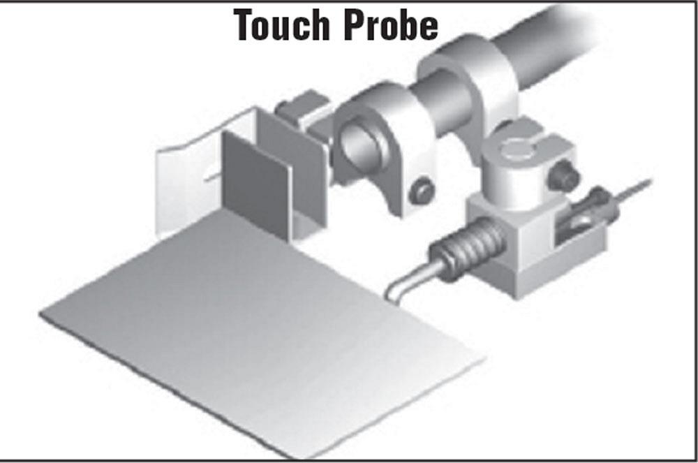
Touch probe sensors, or “whiskers” have a spring-loaded wire that touches the part. When the wire makes contact with the part, it closes or opens the necessary connection, permitting the press to cycle. Like limit switches, they are best-suited to slow operations ( see Figure 2). One of the problems with this type of sensor is that it can be easily altered and bypassed. Often the press operator simply bends the wire so that it is always in contact with the metal.
Light beams and proximity switches and non-contact part detection methods and have shorter reaction times that are better-suited to faster running speeds. Using a non-contact sensor also can reduce or eliminate the use of more cumbersome, mechanical die protection methods. These sensors as well as the absence of a feature.
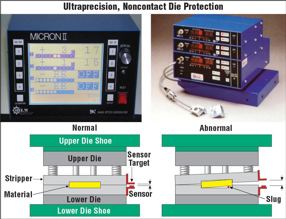
These are one of the most popular and advanced types of systems used in both low-and high-speed stamping operations. With the ability to detect small distances with accuracy up to 0.00001 inch, these monitors measure the gap between any moving die components. By monitoring even minor changes in stripper or pressure pad position or die shut height, this system can detect pulled slugs, double hits, or other abnormal conditions that can result in downtime and die damage.
The limits (distance tolerance sensitivity) also can be changed easily to accommodate a range of stamping dies and speeds up to 3,000 cycles per minute (see Figure 3).
This system works similarly to the voice recognition software that the FBI uses. Every object that produces sound produces a certain sound wave. The same basic concept applies to the sound wave a die produces. Do you remember watching the “Jetsons” cartoons and seeing the sound wave produced by the talking robots? OK, this is not exactly the same, but it is similar.
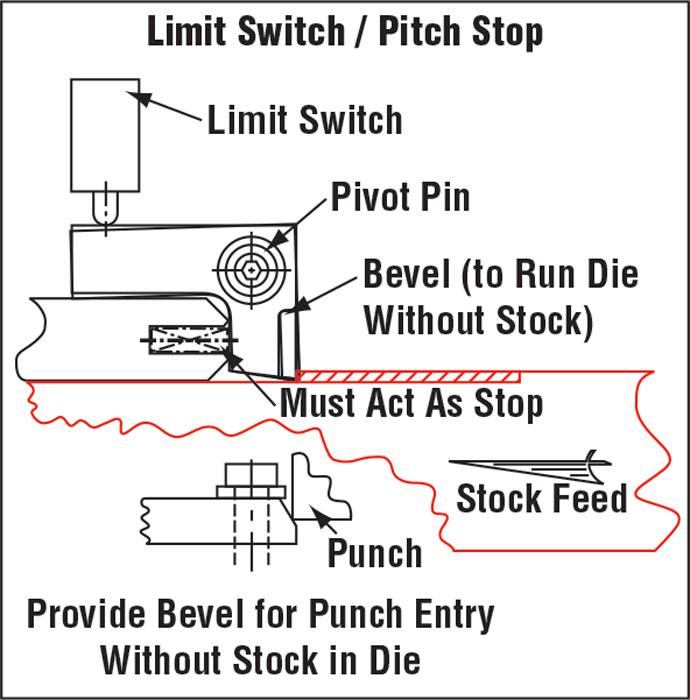
Figure 1
This software essentially measures and plots the sound of a die when it is producing good parts. Like for most sophisticated die protection software, the person in charge of the system sets both upper ad lower control limits with respect to how differently the die can sound and still be considered running effectively.
This system can be set very sensitively so that any differences in the tool sound will stop the press. This could be a punch breaking or pad striking. This system also lends itself to high-speed stamping.
Tonnage Wave Analysis
This method uses load sensors or tonnage monitors mounted under each die station. The required force needed to cut and form the metal is then recorded as a tonnage graph. Like with signature wave analysis, both lower an upper limits are set. If the tonnage exceeds the limit set, the press shuts off. This system can be set so sensitively that it can shut off the press when a dies’s cutting sections get dull and need sharpening.
Until next time… Best of luck!


The Fabricator is North America's leading magazine for the metal forming and fabricating industry. The magazine delivers the news, technical articles, and case histories that enable fabricators to do their jobs more efficiently. The Fabricator has served the industry since 1970.
start your free subscription
Easily access valuable industry resources now with full access to the digital edition of The Fabricator.

Easily access valuable industry resources now with full access to the digital edition of The Welder.

Easily access valuable industry resources now with full access to the digital edition of The Tube and Pipe Journal.

Easily access valuable industry resources now with full access to the digital edition of The Fabricator en Español.
In this episode of The Fabricator Podcast, Caleb Chamberlain, co-founder and CEO of OSH Cut, discusses his company’s...


