Contributing Writer

To determine the height of each draw, you must first calculate the surface area of the finished part. Figure 1 shows the basic equations needed to determine the surface area of any geometric portion of a round cup.
When designing draw reductions, remember that the surface area of the part should remain fairly constant throughout each reduction. It will not be perfectly constant, because a certain amount of surface area is lost and gained by the compression and stretching that occur during the drawing process.
Using designing draw reductions, remember that the surface area of the part should remain fairly constant throughout each reduction. It will not be perfectly constant, because a certain amount of surface area is lost and gained by the compression and stretching that occur during the drawing process.
Using the equations, you can determine mathematically that a cup 2 in. in diameter and 8 in. tall contains 53.398 square in., the surface area of the finished part through the centerline.
In Part I we determined the draw diameters as follows (see Figure 2 ) :
First draw= 4.288 in.
Second draw= 3.001 in.
Third draw = 2.192 in.
Fourth draw= 2 in.
Knowing the diameter of the first draw is 4.288 in., you now can determine its height by calculating the surface area of the top portion of the first draw and subtracting it from the original product surface area.
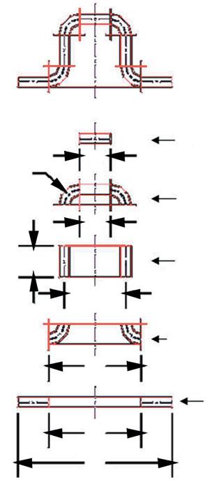
Figure 1
These basics equations can be used to determine the surface area of any geometric portion of a round cup.
The surface area of the top portion of a 4.288-in. -dia. cup is 14.441 sq.in. This amount subtracted from the original surface area of 53.398 sq.in. equals 38.957 sq.in., the surface area that must be present in the vertical wall.
The following equation can be used to determine the draw height of the first draw. It converts the surface area into a wall height using the diameter of the shell:
W= A/ πD
where : W= wall height in inches
A= total surface area present in vertical wall.D= diameter of cup
π= 3.14159
Using this equation, you can determine that the height of the fist draw is 4.288 in. in diameter and 2.892 in.tall.
The same process is used to calculate all of the draw reductions. The second draw is 3.001 in.in diameter. equals 4.596 in.
43.325 sq.in./(3.141 x 3.001 in.) = 4.5696 in. tall
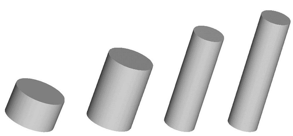
Figure 2
The reduction samples are shown here fully drawn.
Therefore, the second draw is 3.001 in. in diameter and 4.596 in.tall.
Draw No.3 is 2.191 in. in diameter. The surface area of the top portion is 3.770 sq.in., which when subtracted from the addition surface area of 53.398 sq.in equals 49.628 sq.in. This result converted into a vertical wall heigh of a cup that is 2.191 in.in diameter equals 7.211in.
49.628 sq.in./ (3.141 x 2.191 in.)= 7.211 in.tall.
So the third draw is 2.191 in.in diameter and 7.211 in. tall.
Draw No.4 is 2.000 in. in diameter. The surface area of the top portion is 3.142 sq. in. results in 50.256 sq. in. This result converted into a vertical wall height of 2.000 in. equals 8.000 in.
50.256 sq.in/ (3.141 x 2.00 in.)= 8.000 in. tall
So the fourth draw is 2.000 in.in diameter and 8.000 in. tall
Even though this example was for a simple round drawn cup, the basic principles used to calculate draw reductions remain the same regardless of part complexity. The product example used in this article did not have a radius on the top portion of the cup; in reality, most likely a fairly large radius would be on the top. Because of compression and stretch, minor adjustments probably would be needed for each of the draw heights.
Until next time… Best of luck!


The Fabricator is North America's leading magazine for the metal forming and fabricating industry. The magazine delivers the news, technical articles, and case histories that enable fabricators to do their jobs more efficiently. The Fabricator has served the industry since 1970.
start your free subscription
Easily access valuable industry resources now with full access to the digital edition of The Fabricator.

Easily access valuable industry resources now with full access to the digital edition of The Welder.

Easily access valuable industry resources now with full access to the digital edition of The Tube and Pipe Journal.

Easily access valuable industry resources now with full access to the digital edition of The Fabricator en Español.
Seth Feldman of Iowa-based Wertzbaugher Services joins The Fabricator Podcast to offer his take as a Gen Zer...