Contributing Writer

Cutting-punch failure—such as broken pierce punches, chipped cutting sections, sheared trim sections, and chipped buttons—is an age-old problem that inhibits your ability to make a quality product. To resolve this problem, you need to consider numerous factors that could be affecting the life and performance of your cutting die sections and pierce punches.
The first step is to understand the dynamics of die cutting. Metal cutting in a die is the most severe forming operation you can perform. That’s right, forming operation.
During cutting, the metal is being deformed and cold extruded from the rest of the part or strip. This deformation produces the shear zone, or burnished portion, of the cut edge. Once the punch penetrates a certain amount, the metal’s yield strength is exceeded and its ultimate tensile strength met. At this point, the metal fractures, producing the fracture zone (see Figure 1).
In addition, metal cutting not only requires more force than other stamping operations, but it also produces more shock. This shock must be absorbed by the press and the die. To be effective, the die, press, and all the components must absorb shock without breaking down or failing. As the metal’s yield and tensile strength increase, so do the forces needed to form the metal to failure—what is commonly call die cutting.
Believe it or not, the press is one of the most common causes of punch breakage. Make sure your press is well-maintained and in good working condition, and make sure it has minimal deflection rates when under load.
While gap-frame presses (also known as open-back or C-frame presses) work well for low-tonnage cutting, simple bending, and other light-duty operations, typically they are not good for operations requiring both high force and precise punch-to-die alignment. This is because they have greater deflection rates than straight-side presses.
When the tonnage on the ram increases, the amount that the ram deflects with respect to the bolster goes up, which causes poor pierce punch and cutting section alignment. Most gap-frame presses are rated for deflection on a per-inch-of-throat-depth basis. For example, if your gap-frame press has a 24-inch-deep bed rated at 100 tons, and you calculate ram-to-bolster deflection when 100 tons is applied to the press, the ram could be out of parallel to the bolster as much as 0.048 in. This calculation uses a 0.002-in.-per-inch deflection rate. Most older gap-frame presses are rated at 0.0015- to 0.002-in. deflection per inch of throat depth.
Whenever possible, use a straight-side or box-frame press. Deflection on a straight-side press is, on average, 12 times less than on a gap-frame press. Press vibration also is a problem with gap presses, especially when using solid-carbide punches. Although carbide is extremely wear-resistant, its ability to absorb shock and vibration is very poor.
High-speed, ultraprecision presses are very good candidates for carbide tooling, as they are very rigid and vibration-free. They also have low deflection rates compared to a standard press.
Pierce and cutting punches must be able to absorb severe shock without breaking or chipping, and they must have good wear resistance.
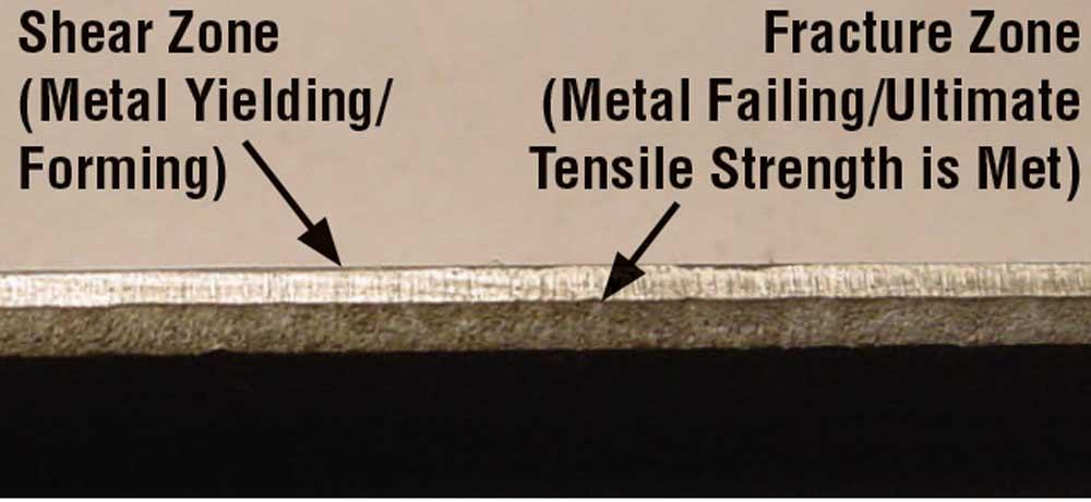
Figure 1
During cutting, the metal is deformed from the rest of the part or strip. This deformation produces the shear zone of the cut edge. Once the punch penetrates the material to a certain amount, the metal’s yield strength is exceeded and its ultimate tensile strength is met. The metal then fractures, producing the fracture zone.
What is the best tool steel from which to produce cutting punches? Consider the thickness and hardness of metal being cut, the cutting clearance selected, and the ratio of punch diameter to material thickness. As the hole diameter gets smaller with respect to the metal’s thickness, the amount of cutting clearance should increase.
For example, if you want to pierce a 0.5-in.-diameter hole in a piece of 0.050-in.-thick fully annealed 304 stainless steel, the typical 12 percent-per-side clearance would be 0.006 in., for a total difference of 0.012 in. between the punch size and the matrix size. This is an acceptable engineered cutting clearance. However, if you want to pierce a 0.050-in.-dia. hole in 0.050-in.-thick fully annealed 304 stainless steel, the ideal cutting clearance is about 18 percent of the metal’s thickness per side, or 0.009 in. per side for a total difference of 0.018 in.
The process of wire electrical discharge machining (EDM) also can cause steel damage that can result in premature punch breakdown. At a microscopic level, wire burning looks like a bolt of lightning coming off the wire and striking the tool steel section. This discharge creates a molten crater of steel lava to be discharged out of the tool steel section.
Essentially, this process meltsair-hardened tool steel while it is submerged in water. The quick quenching process makes the steel very brittle at the wire-cut surface. Using a low-amperage skin cut can help reduce the tool steel damage. For intricate wire-burned punches, the wire-burned section should be stress-relieved after EDM. This tempering process—heating the tool steel section in a furnace to about 50 degrees F below its final tempering temperature—restores the toughness of the cutting edge while maintaining the necessary hardness.
Take the time to learn the physics behind metal cutting. This foundation will help you to make good, data-based decisions when engineering or troubleshooting a stamping die.


The Fabricator is North America's leading magazine for the metal forming and fabricating industry. The magazine delivers the news, technical articles, and case histories that enable fabricators to do their jobs more efficiently. The Fabricator has served the industry since 1970.
start your free subscription
Easily access valuable industry resources now with full access to the digital edition of The Fabricator.

Easily access valuable industry resources now with full access to the digital edition of The Welder.

Easily access valuable industry resources now with full access to the digital edition of The Tube and Pipe Journal.

Easily access valuable industry resources now with full access to the digital edition of The Fabricator en Español.
Seth Feldman of Iowa-based Wertzbaugher Services joins The Fabricator Podcast to offer his take as a Gen Zer...