


Contributing Writer

The experts at STAMPING Journal are here to help you understand the metal flow patterns that can occur during metal drawing operations.
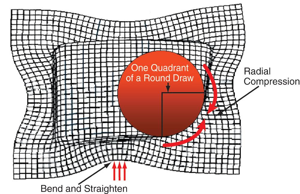
Ears—scallops along the top edge of a deep-drawn part— are the result of varying metal flow patterns that occur during the process (see Figure 1 ). Factors such as the draw ratio, the blank holder force, the metal’s r values, and the frictional values affect the metal’s flow pattern. However, the main contributing factor to earning is the simple displacement of surface area. An explanation of this displacement involves breaking the square or rectangular draw into two different deformation patterns: radial compression and bend and straighten (see Figure 2 ).
A corner of a space draw essentially is one quadrant, or quarter, of a round draw. To produce a round draw, the metal must compress radially as it simultaneously flows inward. This radial compression causes a resistance to flow in the corners of the square draw. This type of deformation—compressing the metal as it flows inward in tension— is known as draw deformation.
If too much metal surface area is forced into radial compression, it will cause a great resistance to flow, resulting in excessive metal stretching and possible splitting. However, if the blank is close enough to the radial profile of the punch, the metal will compress and flow inward, resulting in less metal thinning. This basic relationship between the blank edge and the draw ration (LDR).
During compressive deformation, the flat sheet metal’s surface area is displaced into a radial shape that must consume nearly equal amounts of surface area. In other words, if the metal flow inward 1 linear inch in the corners of the draw. The shell will get taller than 1 in.
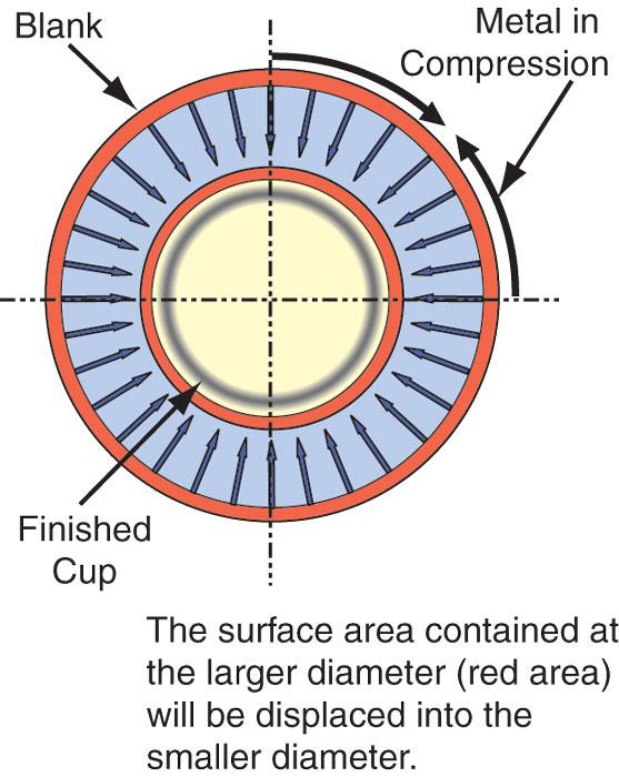
In the production of a round drawn cup, the outer blank edge is a much larger diameter than the drawn cup. The blank edge is a much larger diameter than the draw cup. The blank edge eventually becomes the edge or flange of the finished cup. For this to happen, the surface area contained in the flat blank must be displaced into a smaller-profile corner. The only way the smaller diameter can consume the surface area is to get taller (see Figure 3 ).
The side walls of the drawn box are in bend and straighten deformation. Because there is little or no compression during this deformation mode, the metal flows inward with very little resistance. Resistance can be created by applying more blank holder force in this area or by adding draw beads. This type of deformation—stretching the metal in one direction—is known as plane strain.
During bend and straighten deformation, the ratio of box height to the amount the metal draws inward is 1-to-1. In other words, if the metal moves inward 1 in., the box will get about 1 in. taller. This assumes that no metal flow restrictor (such as a draw bead) is being used, the blank holder force in not excessive, and the metal has very little resistance to flow.
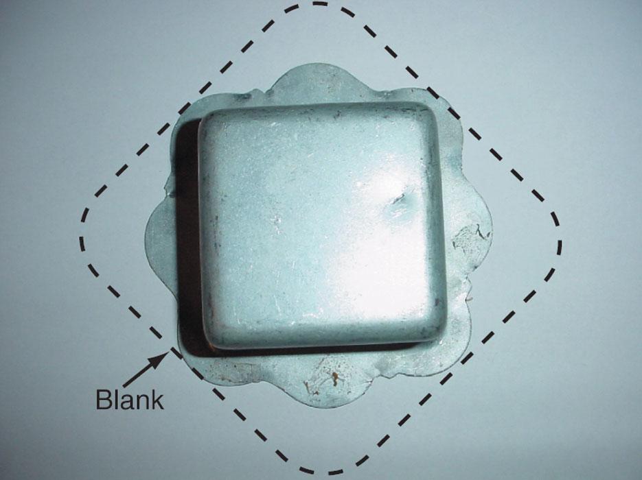
Once you understand the metal flow pattern, the practice of staring with a roundish blank to deep-draw a square product make sense. In the side walls, there is very little resistance to flow. In the corners, there is a greater resistance to flow. Combine these factors with the difference in drawn-in-to-heigh ratios from the side wall to the corners, and a roundish blank is the obvious choice.
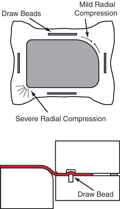
Great difference in metal flow patterns can result in an imbalanced flow. Excessive imbalance can cause product problems such as oil canning or loose metal in the straight walls of a square drawn shell. Severe imbalance problems can result in curved vertical and horizontal walls.
The addition of draw beads can help overcome these differences by slowing down the metal feeding in the side walls, reducing the probability of problems. This is a very common practice and helps to balance the feeding from the corner to the side wall. Draw beads create a restraining force by forcing the metal to bend and unbend before entering the draw cavity and punch (see Figure 4 ).
Rotating the square draw part 45 degrees off-axis to the blank also can help balance metal flow. This is primarily because the rotation changes the draw ratio. In the side walls, more material is outside the punch, while less material is present in the corners (see Figure 5 ).
Draw spotting also can help balance metal flow. Draw spotting, often referred to as a running spot, is the process of grinding the blank holder or die face with respect to the compressive thickening and tensile thinning that occur during the drawing process.
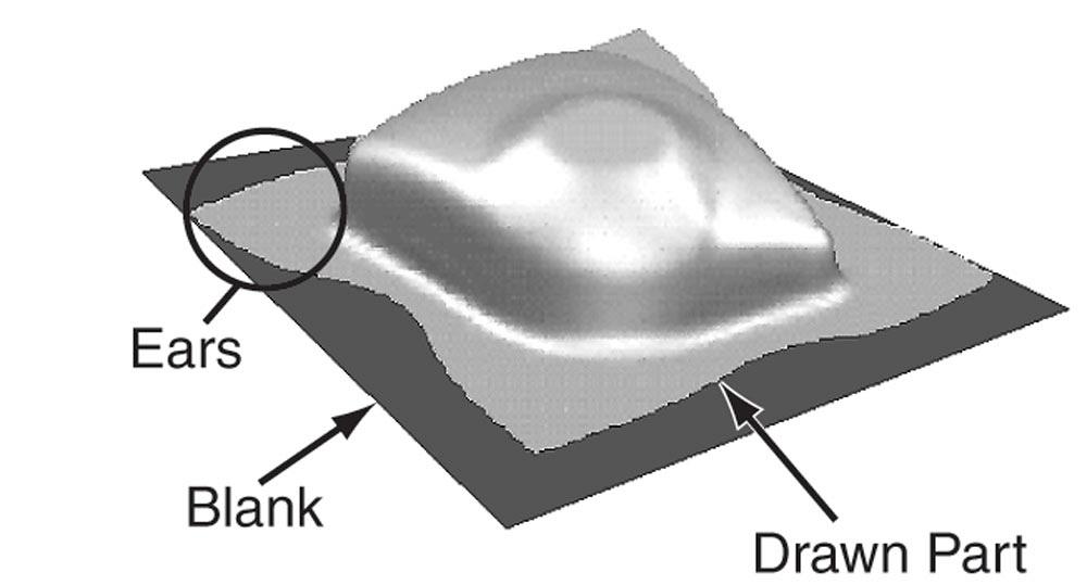
Figure 1
Ears are the result of varying metal flow patterns that occur during the drawing process.
In the corners of a draw and anywhere there is a radial profile, the metal is in compression. Compressed metal trapped between the die face and a blank holder will thicken during the drawing process. Grinding the die face or blank holder with respect to compressive thinking will help to reduce the resistance in the corners of the drawn shell and allow greater blank holder force to be applied to the blank that will end up as the side walls of the drawn shell.
Fabricators often believe that if the part is flat, a perfectly flat blank holder can be used. This is true as long as they are draw-spotted to metal flow conditions, in a process referred to as running the blank holder.
Understanding the fundamentals of metal flow is a key to solving earning problems and loose metal issues. Take the time to understand why things happen in dies rather than just accepting that they do happen. You’ll be on your way to comprehending the true science that dominates the world tool and die.
Until next time… Best of luck!


The Fabricator is North America's leading magazine for the metal forming and fabricating industry. The magazine delivers the news, technical articles, and case histories that enable fabricators to do their jobs more efficiently. The Fabricator has served the industry since 1970.
start your free subscription
Easily access valuable industry resources now with full access to the digital edition of The Fabricator.

Easily access valuable industry resources now with full access to the digital edition of The Welder.

Easily access valuable industry resources now with full access to the digital edition of The Tube and Pipe Journal.

Easily access valuable industry resources now with full access to the digital edition of The Fabricator en Español.
Seth Feldman of Iowa-based Wertzbaugher Services joins The Fabricator Podcast to offer his take as a Gen Zer...


