


Contributing Writer

All too often the process for making the part is adequate,but the die’s ability to feed metal accurately and smoothly from station to station is very poor. This poor feeding can result in jams, miss-hits, die damage, and major frustration for the press operator and die setup personnel.
Three things need to be considered when you are looking more closely at a die’s ability to feed:
Some stampers invest thousands of dollars on a quick die change system in an effort to reduce the die setup time by 15 that cannot be strip-stated easily. Operators can take as long as an hour simply to get the material fed into the die. With a properly designed die, the same setup would take five minutes or less.
Most progressive die damage occurs during the initial die setup, not during production. This usually is because the die designer has placed a greater emphasis on processing the part through the necessary stations and neglected the great responsibility of designing the die to be easily and saftey fed and loaded.
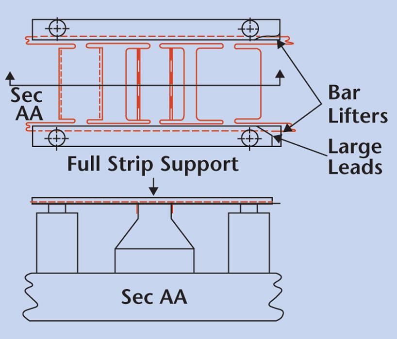
Pay strict attention to items such as large leads on guide and running rails. Keep in mind that feeding a 2-inch-wide strip into a small progressive die is fairly simple, but feeding 72-in. - wide, 0.020-in.-thick material into the die is a different story. Whenever possible, provide a shelf for the material to sit on so the operator doesn’t have to try to hold the material up while feeing it into the die.
Figure 1 shows a die design for easy strip-starting.
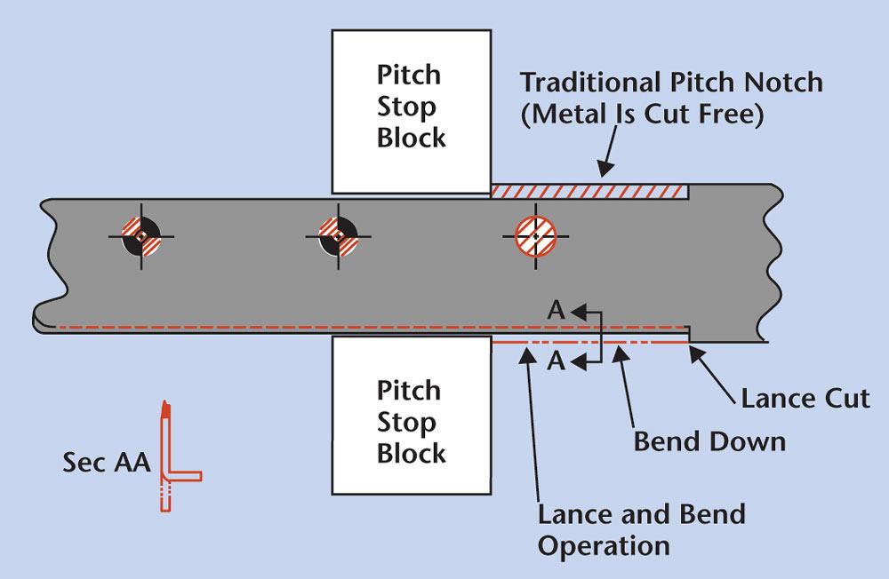
Pitch stop notches, or french notches, often are used to prevent overfeeding and to establish pitch. Although they require the strip width to be slightly wider, they can help to prevent miss-hits and unnecessary die damage.
Removing a portion of the strip edge also removed any edge camber before the metal is fe through the die. Many stampers have done away with pitch notches, which is fine if all the necessary die protection is functioning, the coil feeder is accurate, the strip has very little edge camber, and the operator is well-trained.
Figure 2
shows a lance and bend pitch stop, which makes a pitch notch without creating a slug. This design not only eliminates cutting slugs, but also provides an extra-strong carrier web. It is popular for one-sided carrier strips that either are weak or have a tendency to edge-bend through the die. It works in the horizontal and vertical boundaries of the carrier rail to ensure the strip can be fed forward only (see Figure 3 ).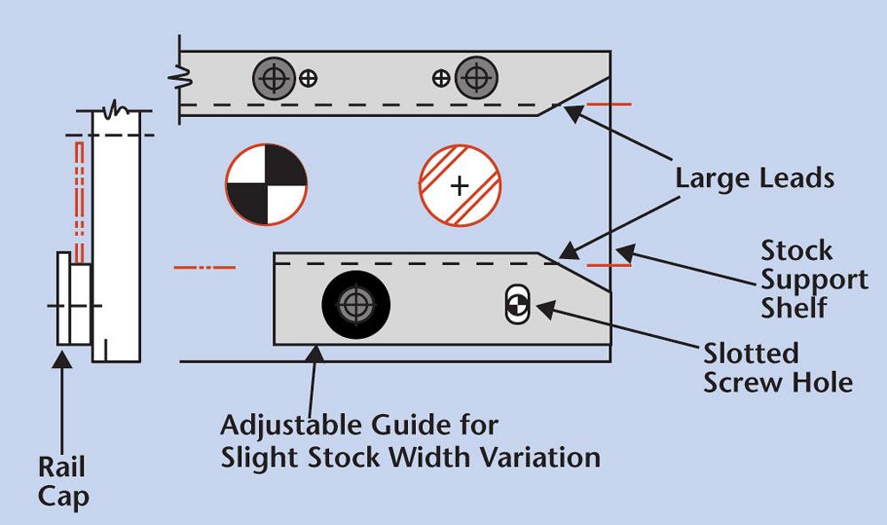
Figure 1
In die design, large leads and adjustable guide rails aid in the strip-starting process. Use caps on running gauges whenever possible.
Many different types of lifter systems can be used for progressive die applications.
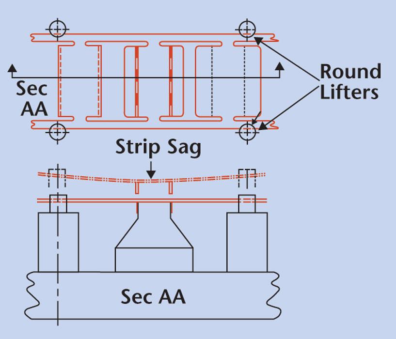
Round lifters can be purchased readily and fairly inexpensive (see Figure 4 ). They work well when the metal gauge is fairly heavy and resist sagging or deflection. They should be placed strategically at supporting intervals.
Round lifters don’t support the entire strip length through the die, so they often allow the strip to sag from lifter to cause metal to fold or buckle on itself. Round lifters also have very small or no leads on them to facilitate strip starting.
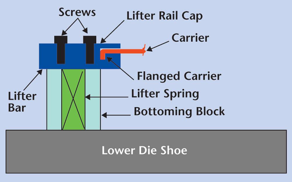
Bar lifters, although more expensive, support the entire strip throughout the length of progressive die (see Figure 5 ). This eliminates sagging and helps reduce or eliminate the probability of the metal folding onto itself. Bar lifters also can be customized to accept a lance and bend pitch stop.
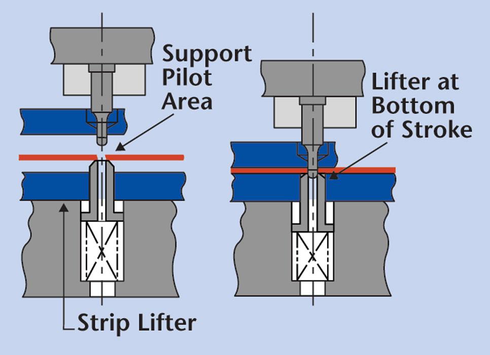
Strip lifters often are used to lift the strip slightly when the part requires very little lift to feed it (see Figure 6 ). They also support the strip during pilot entry.
Make sure that the carrier is wide enough to prevent severe deflection during the feeding process.
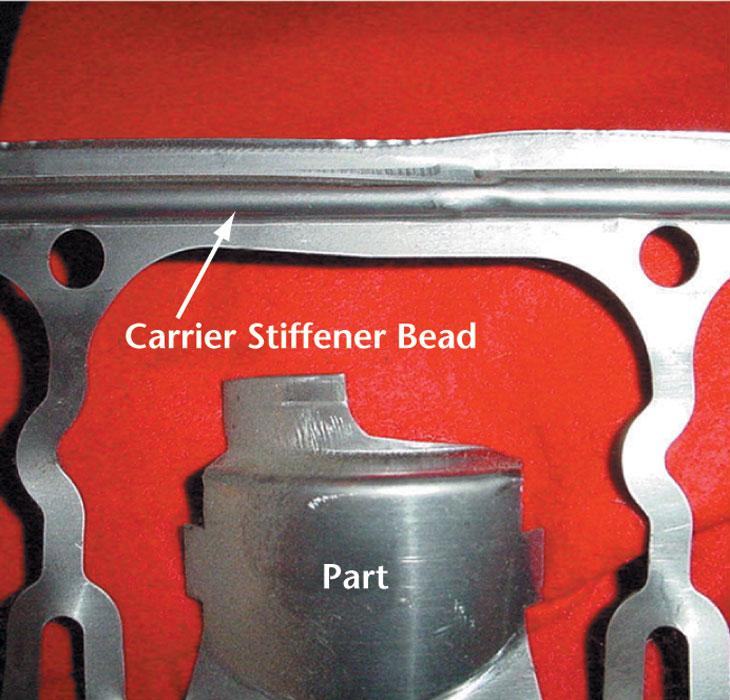
If the metal is very thin and weak, add a a strengthening rib to the carrier web as soon as possible in the die (see Figure 7 ). This rib will stiffen the carrier and allow for much smoother feeding.
Whatever means you use, make sure that the carrier is stiff enough to resist deflection and can be started ad fed through the die very smoothly without hand-ups, and use large leads on all lifter rails and guide rails. Best of luck!


The Fabricator is North America's leading magazine for the metal forming and fabricating industry. The magazine delivers the news, technical articles, and case histories that enable fabricators to do their jobs more efficiently. The Fabricator has served the industry since 1970.
start your free subscription
Easily access valuable industry resources now with full access to the digital edition of The Fabricator.

Easily access valuable industry resources now with full access to the digital edition of The Welder.

Easily access valuable industry resources now with full access to the digital edition of The Tube and Pipe Journal.

Easily access valuable industry resources now with full access to the digital edition of The Fabricator en Español.
Seth Feldman of Iowa-based Wertzbaugher Services joins The Fabricator Podcast to offer his take as a Gen Zer...


