


Contributing Writer

Drawing or Stretching
To select a functional radius size, the first step is to determine whether you forming process uses true drawing, stretching, or a combination.
Drawing is defined as a forming process in which metal is displaced into the forming die through the movement of metal into the forming cavity. This movement often is referred to as plastic flow. Products such as scuba tanks and fuel filter shells are good examples of true drawing (see Figure 1 ).
Stretching, a forming process in which a blank’s surface area is increased through tension stretching, results in metal thinning and is suitable for larger-radii parts, such as automobile hoods, roofs, and other shallow items.
Items such as oil pans are made with a combination of drawing (metal flow) and stretching (tension resulting in thinning and an increase of surface area).
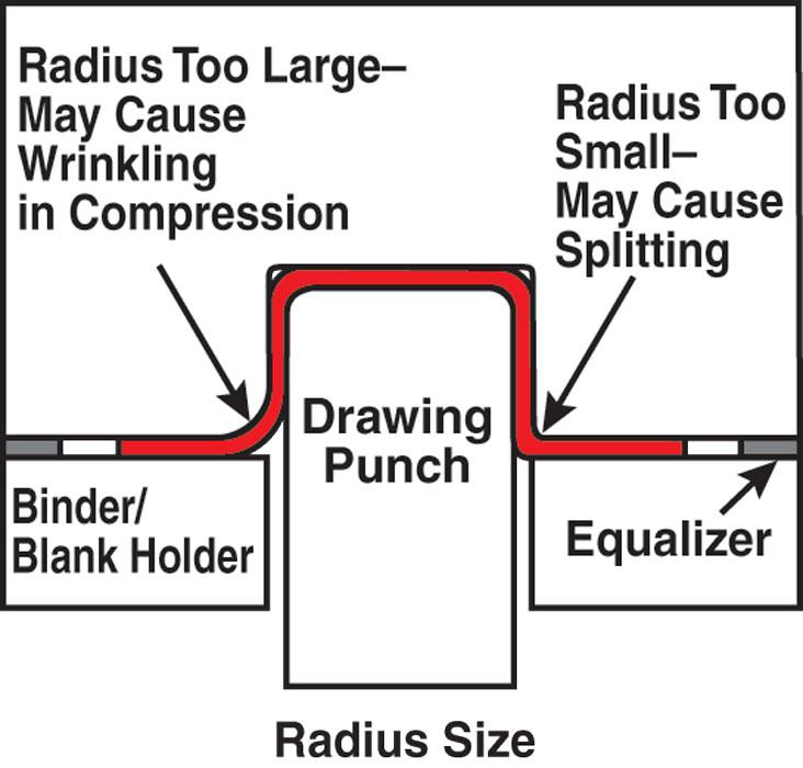
Die Entry Radius
The die entry radius is the radius connecting the cavity wall to the die face. It is one of the most critical radii to size and finish properly (see Figure 2 ). The die entry creates a restrictive force by causing the metal to bend and unbend during the drawing process.
If the die entry radius is too large, the metal is in compression. There is little restrictive force to keep the metal from flowing in, and it might wrinkle in the radial area of the part. This wrinkling can cause cosmetic problems, as well as splitting when the metal is forced to unwrinkle in the walls of the drawn shell. This unwrinkling creates a resistance to flow that results in more stretch.
Different metals require different radii. For instance, drawing aluminum typically requires radii up to one-third larger than the size of radii used when drawing soft steel.
Great caution is required when using a small radius to form materials that retain high strain levels during drawing. For example, forming high-strength steel such as dual-phrase 600 requires a large die entry radius combined with a high blank holder force. This combination will minimize the deformation in the wall as a result of bending the metal over the larger radius and also will strain the vertical side walls of the part, helping to reduce the curling effect that often occurs when the metal is strained over the die entry radius.
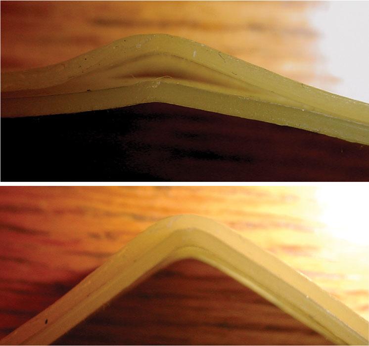
Forming special metals such as laminate also requires larger radii. Bending and unbending laminate material over a small radius may result in delimitation. This is primarily due to the great difference in length of line between the inside layer of metal and the outside layer of metal that is created during the bending process (see Figure 3 ).
Although parts often can be manufactured using radii from one to 100 times the metal thickness, the rule of thumb fro drawing (plastic flow) is to use sic to eight times the metal thickness for steel and eight to 10 times for aluminum.
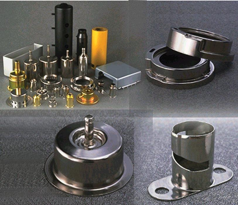
Figure 1
Products such as scuba tanks and fuel filter shells are good examples of true drawing. Photo courtesy of ITW Drawform Corp.
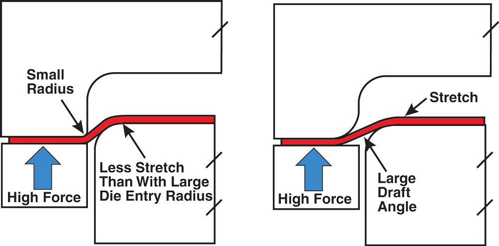
For stretching, the larger the die entry radius, the better the results, because it usually allow more surface area of the metal to be stretched and allows for metal to be pulled and stretched from the product area outward. It also helps to reduce punch radii contact and pull the metal at a shallower angle to the surface of the part. Figure 4 shows metal being stretched to identical depths using a small die entry radius and a larger radius.
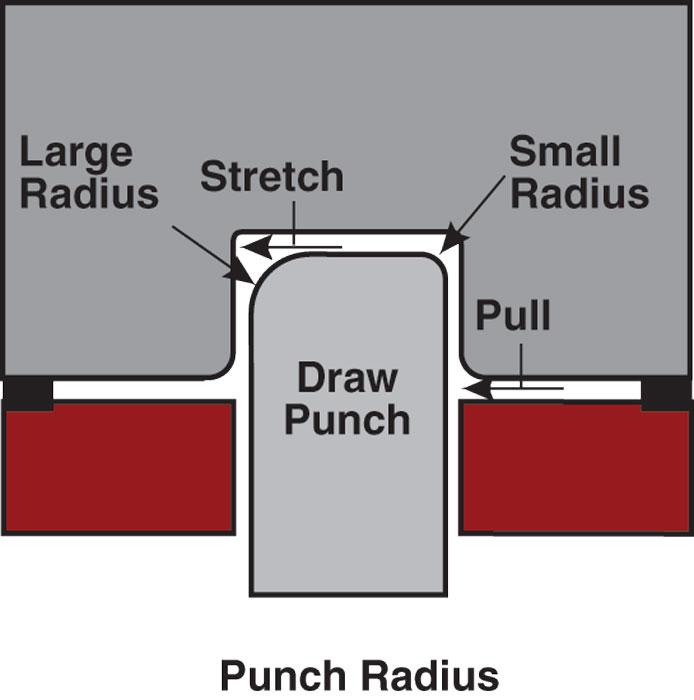
Punch Radius
The punch radius, at the top of the punch, also is critical. The size of the punch radius often determines how much stretch will occur in the product and how much metal will be forced to be pulled from the blank holder.
A very large radius with a high blank holder force or draw beads will force a great deal of stretch to be obtained in the product. A large punch radius with a low blank holder force will result in a combination of flow and stretch. A small punch radius will force the metal to be pulled from the blank holder, and very little stretch will occur in the product area.
A small radius usually is acceptable only when the limiting draw ratio is not being defined. A medium-size punch radius, combined with an acceptable limiting draw ratio, is optimum for stretch distribution in the radial area (see Figure 5 ).
Judgment Call
Selecting the ideal radius for all stretching and drawing operations is at best a judgment call based on many factors. While some guidelines can help you get started, it is best to use some type of finite element analysis or forming simulation software to determine the optimum radii for your drawing or stretching operation.
Until next time… Best of luck!


The Fabricator is North America's leading magazine for the metal forming and fabricating industry. The magazine delivers the news, technical articles, and case histories that enable fabricators to do their jobs more efficiently. The Fabricator has served the industry since 1970.
start your free subscription
Easily access valuable industry resources now with full access to the digital edition of The Fabricator.

Easily access valuable industry resources now with full access to the digital edition of The Welder.

Easily access valuable industry resources now with full access to the digital edition of The Tube and Pipe Journal.

Easily access valuable industry resources now with full access to the digital edition of The Fabricator en Español.
Seth Feldman of Iowa-based Wertzbaugher Services joins The Fabricator Podcast to offer his take as a Gen Zer...


