


Contributing Writer

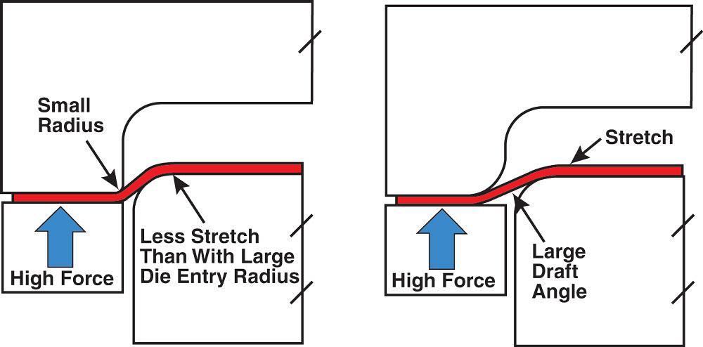
To understand the reason for this, we must first understand the fundamental principles of metal flow. Metal, when forced into compression, has a resistance to flow. Too much resistance to flow results in less feeding of material into the draw cavity and over the punch. This inadequate flow causes more metal stretching, as well as an increased probability of splitting.
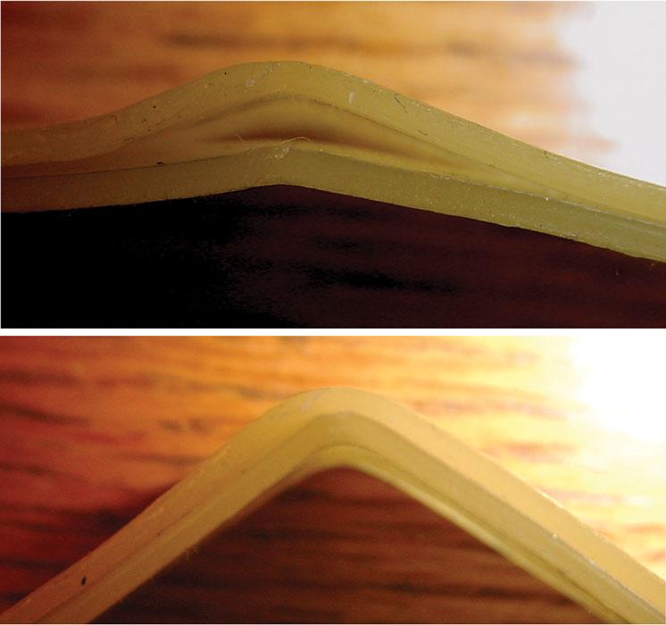
This compression can be seen when drawing axial symmetrical cups or any shape that has a radial profile. When a round cup is formed, the large diemaker must be transformed into a smaller diameter. For this to happen, the metal must flow inward toward the centerline of the cup, and the outside diameter must squeeze together to create the smaller cup circumference. This squeezing is referred to as circumferential compression (see Figure 2 ).
The same phenomenon occurs in the corners of a square or rectangular drawn shell or box. In a square drawn shell, the corners are basically one quadrant, or one-quarter, of a round draw. This geometry forces the metal in bend-and-straighten deformation.
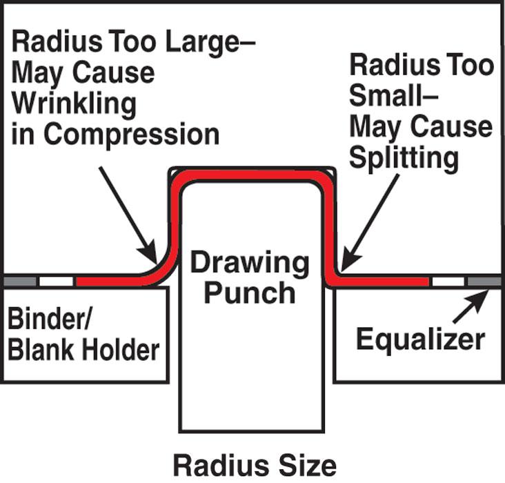
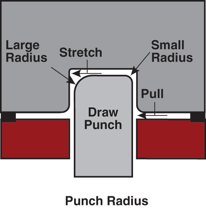
Because there is little or no compression during this deformation mode, the metal flows inward with very little resistance. This difference to deform in an odd shape, resulting in “ears” on the drawn part (see Figure 3 ).Very simply, metal in compression has a resistance to flow, and metal not in compression has very little resistance to flow. The smaller the profile radius, the more the compression; the larger the radius, the less the compression. Increasing, the profile radius reduces the amount of radial compression and increases ability to manufacture deeper draws in a single operation.
Increasing the profile radius to maximize metal flow in a drawing reduction also is common. As with all draw reductions, the amount of surface area needed in the final part must be obtained in the first drawing operation without excessive stretching or thinning of the metal, and increasing the profile radii allows this to be done (see Figure 4 ).
Radii Surface Finish
In most cases, all radii in a drawing operation should be ground accurately and metal-finished to a mirrorlikek surface. The radii should be compete and free from imperfections such as hooks or barbs (see Figure 5 ). The metal must flow freely over the radii.
Don’t confuse shiny with accurate. A radius can be polished to a shiny face finish and still have imperfections that may inhibit the metal flow. The radius must be true and make smooth, flowing transitions.
The radius can be metal-finished starting with rough grinding. This job should be down by the employee with the best grinding skill. Follow the grinding operation with a good stoning job, working down to finer and finer grit stones. Whenever possible, stone and metal-finish in the direction of metal flow. Follow the stoning with emery paper and finally with crocus cloth.
For an extra-polished surface, follow up by using diamond dust on a felt bob mounted in your hand grinder. For large dies, the best way to determine if the radius is accurate is to touch it. Feel vey carefully for imperfections in the radius. The surface finish on the radius can greatly affect friction and metal flow, especially with respect to the die entry radius.
Exceptions to the Rule
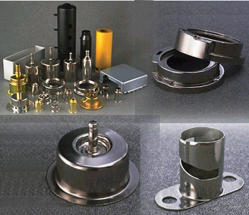
Figure 1
Products such as scuba tanks and fuel filter shells are good examples of true drawing. Photo courtesy of ITW Drawform Corp.
Most drawing radii function best when they are polished to a mirror surface finish, but there are exceptions to this rule. In special cases, it is desirable for the draw punch radius to be left rough to retard metal from slipping around it (see Figure 5 ).
Finish, Accuracy Make the Difference
Selecting the proper die radii doesn’t have to be guesswork. By understanding the simple physics of drawing, you can make good judgments regarding radii size.
Take the time to metal-finish your radii properly. They are the main friction points in your drawing and stretching operations. The surface finish and accuracy of the die radii often make the difference between success and failure when drawing and stretching.
Until next time… Best of luck!


The Fabricator is North America's leading magazine for the metal forming and fabricating industry. The magazine delivers the news, technical articles, and case histories that enable fabricators to do their jobs more efficiently. The Fabricator has served the industry since 1970.
start your free subscription
Easily access valuable industry resources now with full access to the digital edition of The Fabricator.

Easily access valuable industry resources now with full access to the digital edition of The Welder.

Easily access valuable industry resources now with full access to the digital edition of The Tube and Pipe Journal.

Easily access valuable industry resources now with full access to the digital edition of The Fabricator en Español.
Seth Feldman of Iowa-based Wertzbaugher Services joins The Fabricator Podcast to offer his take as a Gen Zer...


