


Contributing Writer

And if you work for the automotive industry, even “once in a great while” is not acceptable. One bad part equals one unhappy assembly plant.
Most complex geometries require at least two drawing operations; especially tall or ornate parts might require as many as 14 or 15 drawing operations. For this reason, splitting problems that occur in secondary drawing or stretching operations are of special concern.
Back to the Beginning
Most of the splitting problems that occur in secondary drawing operations are the result of poor conditions in the first drawing operation. If you have ever performed cylinder drawing reductions, you probably know that to solve a splitting problem in drawing station No.5 requires you to alter of preceding stations.
Increasing the height and changing the radius are common fixes. This approach also applies to shaped drawn parts.
The Law of Constant Surface Area
Whatever surface area is present in your final drawing and stretching operation must also be obtained in the first drawing and stretching operation. Even though the surface area of a blank changes throughout the drawing and stretching operation, try to keep it constant value for engineering purposes.
The reason a part splits in the second forming die is that it has been stretched beyond its capability. This excessive stretching occurs when the surface are obtained in the first forming operation area wasn’t sufficient to make the finished part geometry. The trick is to get that needed surface area in the first die while preventing localized thin-out.
Drawing Versus Stretching
You can obtain the needed surface area either through stretching or drawing.
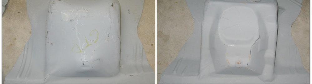
Figure 1
Deep-formed parts often require both drawing and stretching.
Drawing is the displacement of a blank’s surface area into an alternate geometry via tension and metal flow. During true drawing, there is very little thinning of the metal; in some cases, even thickening occurs.
Stretching is the increase of surface area via tension. During stretching, the metal alway gets thinner, increasing the risk of failure.
Therefore, there is a no maximum depth that a part can be drawn, but there is a a maximum depth that it can be stretched. However, because drawing uses tension to pull the metal into the drawing cavity, some mild stretching does occur. Very little drawing occurs during stretching.
Sometimes drawing and stretching operations are required to fabricate contoured, deep formed geometries (see Figure 1 ).
Let’s assume that your first operation is mostly drawing, and very little stretching in occurring. The goal of the first step should be to get the same amount of the surface area into the first draw shell as in the second drawing die.
This can be done by:
Stretching in the First Die
Getting the needed surface area in a stretching die is far more complicated than getting it in a drawing die. This is because of the metal thinning that occurs during stretching. The key to getting the needed surface area in the first form during stretching is to choose a punch shape that forces the metal to distribute the stretch as evenly as possible over the entire forming punch geometry.
Shaped punches with small radii will most likely result in server localized thin-out in the radial area. Therefore, the punch should have the largest possible radius. Try to gain the surface area that you need by stretching it as evenly as possible. The key is to obtain surface area by forcing good stretch distribution (see Figure 2 ).
When stretching metal:
The Bottom Line
So many toolmakers spend countless hours working on the die where the split occurred, only to find out that the problem could be traced back to the first operation. A minor alteration to the first form can save a great many headaches later on.
Until next time… Best of Luck!
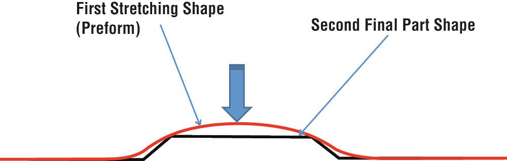
Figure 2
Prestretched material is displaced into an alternate geometry using the constant surface
area rule.


The Fabricator is North America's leading magazine for the metal forming and fabricating industry. The magazine delivers the news, technical articles, and case histories that enable fabricators to do their jobs more efficiently. The Fabricator has served the industry since 1970.
start your free subscription
Easily access valuable industry resources now with full access to the digital edition of The Fabricator.

Easily access valuable industry resources now with full access to the digital edition of The Welder.

Easily access valuable industry resources now with full access to the digital edition of The Tube and Pipe Journal.

Easily access valuable industry resources now with full access to the digital edition of The Fabricator en Español.
Seth Feldman of Iowa-based Wertzbaugher Services joins The Fabricator Podcast to offer his take as a Gen Zer...


