


Contributing Writer

As a consultant and instructor, I’m often asked if round, drawn shapes are less difficult than contoured shapes. Although numerous factors determine difficulty, with minor exceptions the answer is yes, round draws typically are easier to process and troubleshoot than contoured shapes.
To understand why round draws typically are simpler than contoured shapes, you first must understand how metal flows. In a round draw, using a round blank, all the inward flow of metal is axial-symmetrical, which means it is the same around the entire perimeter of the cup or round drawn shell. The amount of compressive thickening also is uniform, which means the distance between the drawing pad (binder) and the die face is uniform. This can be achieved by adjusting the draw pad equalizers to a set distance.
As long as the blank is not too large with respect to the drawing punch diameter, and the die entry radius is the proper size and geometry, the metal will flow in freely, and very little thinning will result. Because round drawn shells obtain the final geometry mostly through metal flowing inward, they can be drawn out of a variety of metals, from high-elongation metals like low-carbon steel to low-elongation materials like aluminum.
Contoured and nonround shapes must be made from low-elongation metal because typically a portion of the parts geometry is obtained by stretching the metal. This same idea applies to deep-drawn parts that do not have an even profile radius.
Unlike round drawn shells, the metal flow in a nonround drawn shell or contoured part will not have an even amount of metal flow. Instead, the metal flow is greater in some places and less in others. This difference in metal flow is the direct result of varying part shapes and geometry.
Any time the part geometry has a profile radius, the metal is forced to go into radial compression. A round cup has a uniform profile radius. Remember, compression creates a resistance to flow. The amount of radial compression that occurs depends on the size of the profile radius. As the profile radius gets smaller, the amount of compression increases; as the compression increases, so does the resistance to flow; as the resistance to flow increases, more metal stretching occurs. Overstretching the metal can result in splitting or fracturing.
If the amount of compression varies around the perimeter, so will the amount of compressive thickening. A difference of as little as 0.0005 inch can be enough to create wrinkling or splitting problems, both in the part and on the draw pad or die face surface.
This is especially true when attempting to deep draw very thin-gauge, low-elongation metals such as automotive grades of aluminum. Compared to steel, aluminum typically has about half the elongation. Thin gauges of metal are also very prone to wrinkling because they lack the thickness or stiffness to resist wrinkling. If the metal is allowed to wrinkle on the drawing pad and is pulled into the die cavity, the wrinkle may cause splitting.
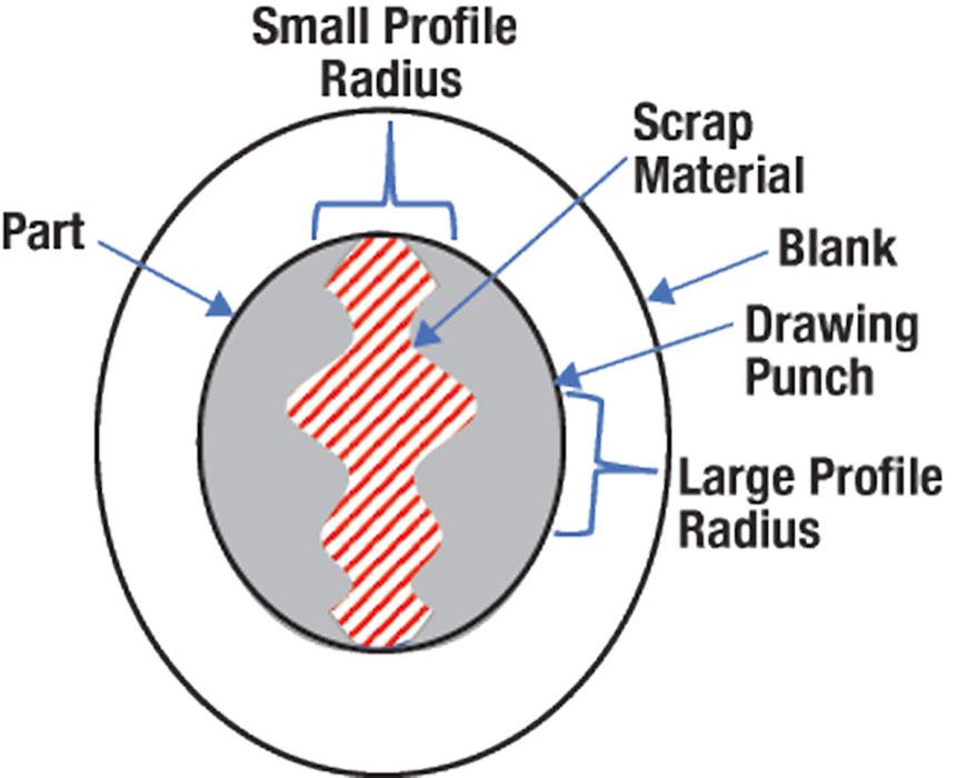
To produce two deep-drawn parts nested on a common drawn part, you would make a single drawn shell and split it into two parts. The normal process would be to nest the parts so that production of each part uses as little material as possible. However, you have to consider the metal’s capabilities when choosing the drawing punch profile.
The part nest in Figure 1, for example, would be acceptable if the metal had good ductility and elongation, but a risky choice for materials such as thin-gauge aluminum because the profile of the draw punch is not axial-symmetrical. Metal flow amounts will vary because of differing amounts of compression. Parts processed in this manner often are sensitive to minor changes in sheet material, lubrication, drawing pad pressures, and forming speeds.
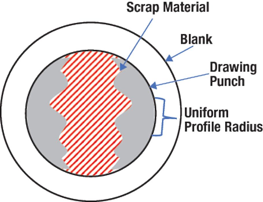
Although more metal is needed to produce the parts, nesting the parts on a round shell will simplify the process and reduce the forming severity of the part (see Figure 2). My advice: Disregard the wasted material as the natural cost of making a deep-drawn part from this low-ductility material. Yes, the metal costs money, but what good is a die that doesn’t work or produce a satisfactory part?


The Fabricator is North America's leading magazine for the metal forming and fabricating industry. The magazine delivers the news, technical articles, and case histories that enable fabricators to do their jobs more efficiently. The Fabricator has served the industry since 1970.
start your free subscription
Easily access valuable industry resources now with full access to the digital edition of The Fabricator.

Easily access valuable industry resources now with full access to the digital edition of The Welder.

Easily access valuable industry resources now with full access to the digital edition of The Tube and Pipe Journal.

Easily access valuable industry resources now with full access to the digital edition of The Fabricator en Español.
Seth Feldman of Iowa-based Wertzbaugher Services joins The Fabricator Podcast to offer his take as a Gen Zer...


