


Professor and Director
Getty Images
Galling is a type of die surface damage that differs from the typical deterioration of a surface caused by abrasive wear. Galling is caused by the adhesion of particles that separate from sheet metal during its sliding along the die surface. It causes scratches and splits on the workpiece surface, as well as adhesive wear of stamping dies. If even minor galling appears on tools during a high-volume stamping operation, die maintenance is required immediately to prevent failure of the stamped parts.
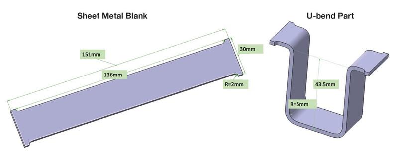
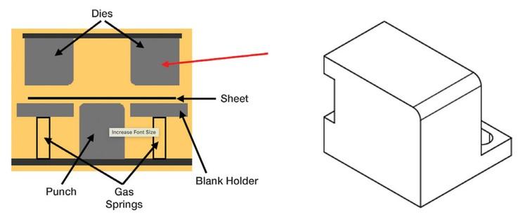
Researchers at Oakland University’s Center of Advanced Manufacturing and Materials (CAMM) recently used the U-bend process (see Figure 1) to investigate die wear behavior during room-temperature stamping of aluminum alloy sheet AA5754, typically used for lightweight automotive structural parts.
The strip was blanked from a 2.5-mm-thick and 151-mm-wide coil lubricated with 61AUS (mill oil) lubricant at 50 mg/ft.² average weight. The depth of draw of the U-bend part was 43.5 mm, and the inner radius was 5 mm. In the final part, flange length was variable, depending on the clamping force, friction, and material stretching.
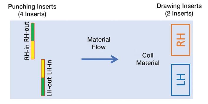
A schematic of the progressive die for stamping the U-bend coupons is shown in Figure 2. Initially the portion of the perimeter along the 26-mm width was blanked out of the coil. The tabs were preserved in the coil for location purposes and to allow movement of the blank inside the progressive die. At the final position, the tabs were trimmed off, followed by stretch bending of a U-bend part (see Figure 3). The blank holder was supported by gas springs charged from a nitrogen tank to predetermined pressure.
The researchers used two die materials—D6510 cast iron and S0050A cast steel—for forming inserts used to form U-bend coupons. Initially both materials were heat-treated to 54 HRC and then hard-chromed.
One of the critical parameters to achieve comparable die wear conditions is the binder force applied via nitrogen cylinders. Several levels of average pressure were tested during U-bending. Initially a flat blank holder applying the clamping force to the whole flange of the U-bend coupon was employed. In this case, the clamping pressure applied to the formed coupon varied from minimum at the beginning to a higher level at the end of the stroke. This difference in clamping pressures was determined by the sheet metal inflow into the die cavity and decrease in the area of the flange under the flat blank holder. The binder force in this case was 6.8 kN, applied to each side of the flange of the U-bend coupon.
Assuming that the nitrogen pressure in the cylinder remained unchanged, the average binder pressure at the beginning of the forming process was 4.8 MPa, and at the end of the stroke it was 12.9 MPa. In such a configuration, 50,000 U-bend coupons were stamped with no galling occurring on the forming inserts. During this experiment, there were random cases of particles separating from the blank and temporarily staying on the die surface, but the particle location was variable, and most of the stamped U-bend coupons had no scratches. So this condition was considered safe from galling.
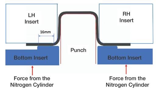
To determine the galling threshold, the researchers increased the blank holder pressure by reducing the area of contact with the binder and increasing pressure in the nitrogen cylinders (see Figure 4). The blank holder pressure in this case did not change, except for a slight increase of pressure in the nitrogen cylinder itself. The area of the flange to which the binder force was applied in this case was constant.
They found the galling threshold to be greater than 30 MPa of contact pressure. The tested conditions were 31.6, 37.9, and 39.5 MPa, corresponding to binder forces of 13.5, 16.2, and 16.9 kN. At each level of the binder pressure, 3,000 U-bend coupons were produced to determine the galling threshold. Maximum level of pressure was defined for each set of inserts as the highest stable pressure with no fracture initiation in the U-bend coupon.
To evaluate die wear and potential galling, researchers measured the die surface with a Bruker optical profilometer. The results were reported using roughness Sa, which expresses, as an absolute value, the difference in height of each point compared to the arithmetical mean of the surface.
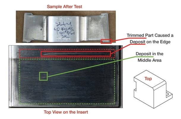
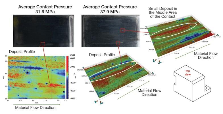
Galling thresholds were determined in two zones: at the edge and in the middle (see Figure 5). Pictures of the hard-chromed S0050A insert and deposit profiles after 3,000 strokes at 31.6 MPa, and then after 3,000 strokes at 37.9 MPa average contact pressure levels, are presented in Figure 6. A deposit in the middle area of the contact zone was observed at 37.9 MPa. The maximum stable condition for S0050A die material was 37.9 MPa; attempts to increase pressure led to sheet metal failure at the die entry radius.
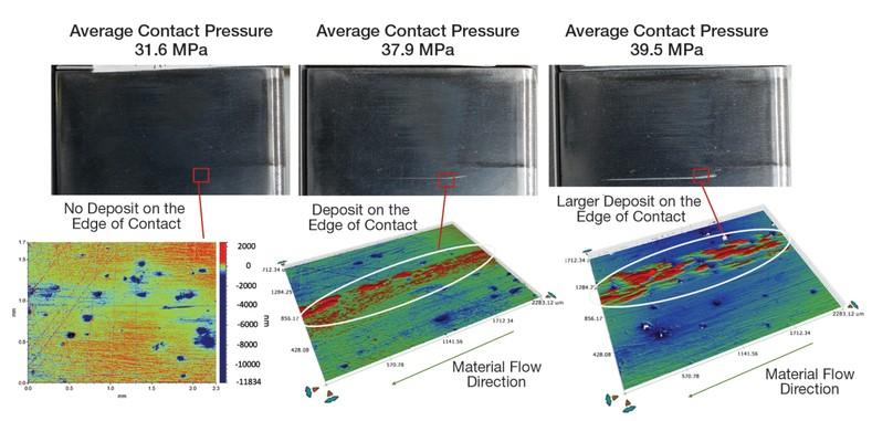
Pictures of the hard-chromed D6510 insert and deposit profiles after 3,000 hits at 31.6, 37.9, and 39.5 MPa average contact pressure levels are illustrated in Figure 7. No deposit on the edge contact area was observed at 31.6 MPa. The first deposit appeared at 37.9 MPa, making this pressure level a galling threshold. At 39.5 MPa average contact pressure, a larger deposit was observed on the edge contact area.
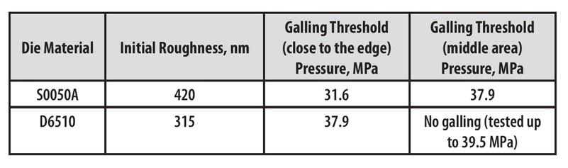
The results of galling threshold measurements after 3,000 stamping cycles at various average contact pressures are summarized in Figure 8. Initial roughness of the hard-chromed D6510 inserts was lower than hard-chromed S0050A, which could be one of the reasons why the galling threshold level was higher for the iron.
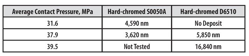
Figure 9 shows the results of measuring maximum deposit height at the edge contact area on the inserts’ surface after 3,000 stamping cycles at various average contact pressure. Hard-chromed D6510 started getting deposit accumulation at higher pressures than S0050A, but the height of the deposits was larger with D6510.
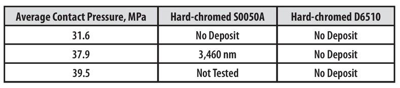
Maximum deposit height in the middle contact area on the inserts’ surface after 3,000 stamping cycles at the various average contact pressures is shown in Figure 10. Hard-chromed S0050A started getting deposit accumulation at 37.9 MPa. Hard-chromed D6510 had no deposit in the middle contact area within the tested range of contact pressures, which was limited by splitting of the sheet at the die entry radius as contact pressure increased.
To understand why the hard-chromed D6510 inserts performed better than the hard-chromed S0050A inserts, the researchers studied friction conditions with the same sheet and insert materials employing the methodology described in “Measuring friction for stamping of UHSS”. They found the average coefficient of friction (COF) between AA5754 strips and hard-chromed D6510 inserts using 50mg/ft.2 61AUS lubricant to be 0.045; between similar aluminum samples and hard-chromed S0050A inserts, the COF was 0.08. This significant increase in COF is one of the reasons for the lower galling threshold for the hard-chromed S0050A insert.
Both tested combinations had galling on the edge contact area of the insert, with hard-chromed S0050A at 31.6 MPa and hard-chromed D6510 at 37.9 MPa. The difference in initial roughness of the inserts, as well as higher friction measured for S0050A inserts, could be the reason for the different galling threshold levels.
Hard-chromed D6510 showed no galling in the middle contact area all the way to maximum achievable pressure of 39.5 MPa without fracture initiation in the sheet. Hard-chromed S0050A showed galling in the middle contact area at 37.9 MPa.
Hard-chromed D6510 started getting deposit accumulation at a higher pressure than S0050A, but the height of the deposits was larger.
Reference
E. Rabinowicz, “Friction seizure and galling seizure,” Wear, Vol. 25, No. 3 (1973), pp. 357–363.

Professor and Director
Oakland University Center of Advanced Manufacturing and Materials (CAMM)


The Fabricator is North America's leading magazine for the metal forming and fabricating industry. The magazine delivers the news, technical articles, and case histories that enable fabricators to do their jobs more efficiently. The Fabricator has served the industry since 1970.
start your free subscription
Easily access valuable industry resources now with full access to the digital edition of The Fabricator.

Easily access valuable industry resources now with full access to the digital edition of The Welder.

Easily access valuable industry resources now with full access to the digital edition of The Tube and Pipe Journal.

Easily access valuable industry resources now with full access to the digital edition of The Fabricator en Español.
In this episode of The Fabricator Podcast, Caleb Chamberlain, co-founder and CEO of OSH Cut, discusses his company’s...


