


Professor and Director
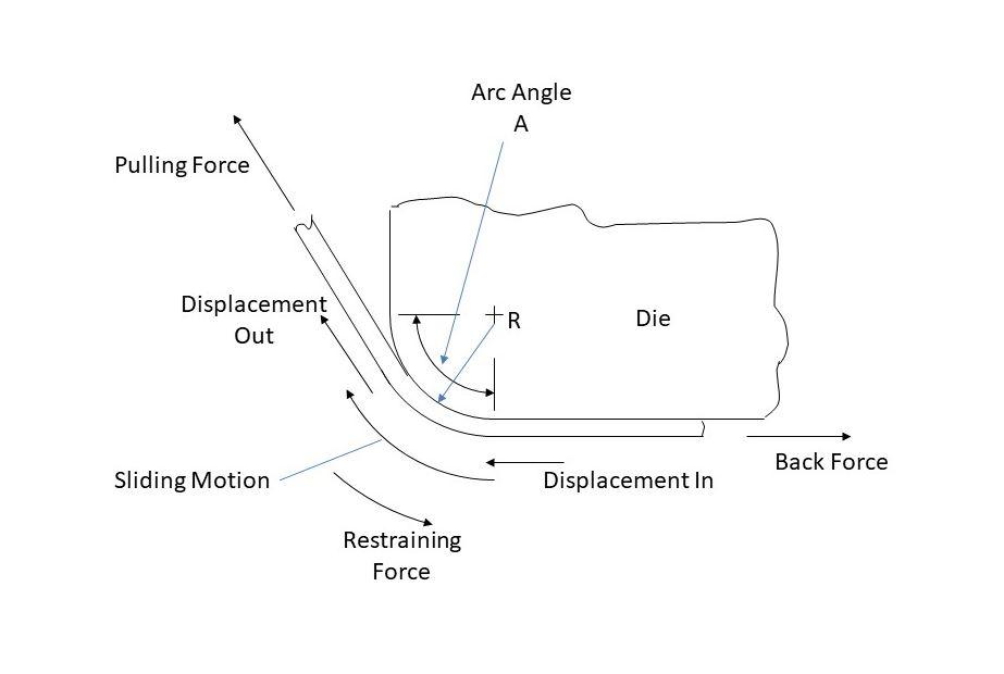
FIGURE 4. This is the basic forming model for calculating what happens as the sheet metal is wrapped over and slid along a die radius.
Editor’s Note: Read Part I.
When the displacement arrows are plotted to scale on the product’s CAD data and viewed in the plan view, adjacent arrows will be either parallel but of different lengths (shear), diverging from each other (stretch), or converging toward each other (draw). From the measurements, the strain necessary to make the displacement happen can be calculated quickly and easily. These calculated strains can then be plotted on a forming limit diagram to assess their feasibility. These strains help the designer decide how the sheet metal should slide across the die face and specify target strains for the design to impose.
The strains corresponding to these displacements are not necessarily principal strains (major or minor strains) but the strains (stretching) needed in those directions in the sheet metal to achieve the product geometry. Therefore, these strains cannot be directly compared to a circle grid analysis or to principal strain maps from a simulation. The strains are at the specific point along and normal to the specific wire of the wire frame analysis. Once the designer has placed the neutral lines and other wires, plotted the displacement arrows, and established the target strains and displacements needed in the product region of the sheet metal, the forming strategy is completed.
The next step is to define the forces in terms of the strain pair that will give the force as the true stress times the thickness (the width assumed to be 1.0 mm), as well as displacements of the forming strategy that must be imposed onto the edge-of-part, indicated by the arrows F and D at the ends of the wires shown in Figure 3. The displacement (D) is simply the accumulated sliding motion in millimeters that must be accommodated at that point, which can be sliding out of the product (+), sliding into the product (-), or no sliding motion (0). The force (F) will be calculated based on the strain that must be imposed at the point to get the strain.
The designer’s spreadsheet employs the analytical method based on membrane theory of plasticity to calculate the strains, stresses, and forces along the wires of the wireframe to establish the energy continuum and the length ofmaterial that must exist in the wrap adjacent to each wire. The thickness changes are calculated as the conservation of volume to the two in-plane strains, and the wire forces are calculated by multiplying the true stress by the thickness and by the width of the wire (set at 1 mm in the spreadsheet for convenience).
The first arc starts at a neutral line with a strain assigned from the strategy and zero displacement. As the material stretches, it slides along the arc, and as it bends to take the shape of the arc, the increment of force required to cause the bending is added to the pulling force necessary to achieve the strain. This increment of stress is calculated using the equivalent energy approach. Similarly, as the sheet metal slides along the arc, the friction force resisting the sliding is added to the pulling force using the rope-and-pulley formula, and finally the unbending force is added. The maximum strain is just past the output tangent point (see Figure 4).
The “displacement out” and corresponding “strain out” are the result of the pulling force and the force in the plane of the sheet normal to the wire length of a hypothetical extension of sheet metal that had never touched the die and so never experienced bending or through-thickness stress. The “strain out” is the input to the next arc. If at any time the calculated required pulling force cannot be achieved, the designer must find and fix the problem, as the original forming strategy cannot be achieved.
It should be noted that no knowledge of the die is required to get to this point, and, since it is accomplished in a wireframe abstraction of the product geometry manually input into the spreadsheet, it can be accomplished in the vehicle development’s architecture phase when much, if not all, of the stamping is still in wireframe (albeit not the same wireframe as the abstraction for die design). If done then, it will be moved even further up the vehicle development process to where changes to the product design for formability reasons are the easiest, fastest, and least expensive to make.
The die features, shown in the purple, blue, and green lines in Figure 1, can now be calculated from the strains and displacements required (the continuum) at the edge-of-part.
In theory, those dimensions can be calculated with no knowledge of the part geometry other than the 3D edge-of-part line, its surface normals, and the strains and displacements. In practice, it will be accomplished by continuing to extend the wires of the wireframe to the edge of the blank. Usually, from a practical standpoint, the calculations end at point X (see Figure 1). A straight-line extension through the binder following die design rules is adequate, and the spreadsheet will give the restraining force that must be imposed by the draw bead. An analytical approach presented in Mechanics of Sheet Metal Forming or multiple other analytical or numerical models can be employed for this purpose.
It always makes sense to correlate the analytical or numerical results on draw bead restraining forces with experimental data. Some examples can be found here. Taking one of the mentioned approaches, the designer can determine the draw bead dimensions necessary to achieve the bead force and the displacement across point X as given by the spreadsheet. The material sliding through the bead adds stretching of about 10%, depending on the depth of the bead and sharpness of the bead radii. So, calculating the location of the edge of blank is straightforward, and all other geometries are usually defined by the die standards.
The wrap surface must be designed. The shape of the wrap usually is a complex developable, and its creation is a CAD function. Achieving the lengths of lines calculated from the spreadsheet in the wrap defines the shape of the binder. Constructing the wrap surface is all geometric CAD work, and some CAD systems automate the process. There is also a reconciliation process, as the wrap surface rarely falls on all the X points. There are many shapes of the die in the purple line (see Figure 1) that will satisfy the energy continuum, and the designer will have originally constructed the one that results in the minimum blank. But it can be changed to one of the other shapes to reconcile a miss-fit to the wrap at point X as long as certain geometric relationships are maintained. The reconciliation process becomes a CAD function only.
When the displacement at point X is zero, the bead in the binder can be a square lock bead, which is the most desirable because it eliminates several processing variables. But if in the reconciliation process zero displacement cannot be achieved without excessive blank size, a draw bead must be specified and dimensioned.
The wireframe for the sheet metal outside of the edge-of-part is now attached to the original product CAD data and surfaced (or fitted with a sheet solid), and the finished design of the drawn form can be simulated as a check and validation of the design.
The next step is to extract the die faces from the drawn form, accounting for elastic deformation of the sheet, which can be estimated as the average final forming stress divided by the elastic modulus of the sheet metal. The sheet metal will shrink that amount when the die opens and the final forming stresses relax. The extracted die faces should contact the sheet metal only on inside radii, but run-off surfaces and profile lines must be added around the edges. Also, all the die faces for the line dies must be extracted and clearances, offsets, shear, and travels defined. More detailed discussion and examples of the proposed design algorithm can be found in the SAE technical paper “A Direct Engineering Approach to Draw Die Binder Development Design.”
CAD files should be developed of all the die face elements and sheet metal pieces—since they will enter a die and leave a die—including the trimmed scrap pieces.
In the process of designing the die face, the designer becomes aware of a host of issues that will be important to the die tryout team, diemakers, the press line diesetters, and troubleshooters. These include drawings showing the location of circle gridding on the blank, critical strains at locations on the product, and other instructions and warnings.
References
E.A. Herman, “A Direct Engineering Approach to Draw Die Binder Development Design,” SAE technical paper 2020-01-0952, 2020, doi:10.4271/2020-01-0952.
Z. Marciniak, J.L. Duncan, and S.J. Hu, Mechanics of Sheet Metal Forming (Oxford, U.K.: Butterworth Heinemann, 2002).

Professor and Director
Oakland University Center of Advanced Manufacturing and Materials (CAMM)


The Fabricator is North America's leading magazine for the metal forming and fabricating industry. The magazine delivers the news, technical articles, and case histories that enable fabricators to do their jobs more efficiently. The Fabricator has served the industry since 1970.
start your free subscription
Easily access valuable industry resources now with full access to the digital edition of The Fabricator.

Easily access valuable industry resources now with full access to the digital edition of The Welder.

Easily access valuable industry resources now with full access to the digital edition of The Tube and Pipe Journal.

Easily access valuable industry resources now with full access to the digital edition of The Fabricator en Español.
In this episode of The Fabricator Podcast, Caleb Chamberlain, co-founder and CEO of OSH Cut, discusses his company’s...


