


Design Engineer and Press Brake Specialist
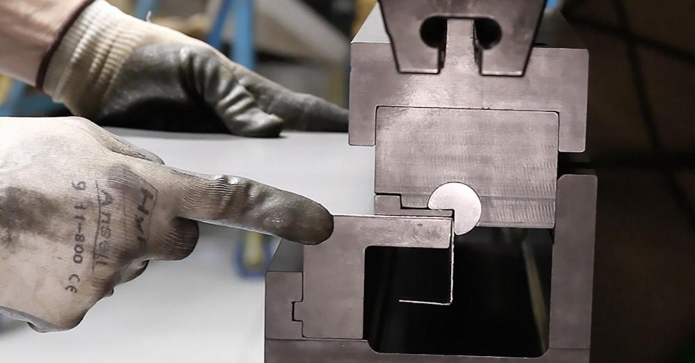
Figure 1
A large cavity in the die allows the operator to perform multiple flange bends. The sheet remains in the horizontal position.
It’s a common sight: An operator slides a sheet against the press brake backgauge, steps on the pedal to initiate the bend cycle, and swings the large sheet high to bend an edge flange. The operator’s back and shoulders may hurt a lot after a shift of doing that. After so many bends, he also may not hold the sheet steady as it whips up during the bend cycle. This may cause the sheet to distort slightly and, as a result, throw the bend angle and radius out of tolerance.
In these cases, horizontal bending—that is, where the sheet remains horizontal during the bend cycle—can help. Special tool types abound, but in general the press brake has two categories of horizontal bending tools: wiping tools and rotary-style tools (see Figures 1 and 2).
The tool size governs the flange depths possible; up to 5-in. flanges are possible in some cases, though deeper flanges require larger (and more expensive) horizontal bending tools. Still, for the right application, using such press brake tools can eliminate the need to follow the sheet upward during every bend cycle. That’s something operators can appreciate.
Wiping tools consist of a forming punch that moves next to a stationary die. The punch essentially “wipes down” the sheet against the die, which governs the inside bend radius and bend angle (see Figure 3). The space between the adjacent punch and die equals the material thickness. The maximum flange depth is governed by the size of the tool cavity, while the minimum flange depth should generally be at least three times the material thickness, depending on the material.
Wiping is essentially a bottoming operation, and each die set is made for a specific material type, thickness, bend angle, and radius. Bend angles usually are 90 degrees, but some custom wiping tools can be made to accommodate other angles.
During the bend cycle, the tool wipes the material down around the die. In bottom bending with conventional tools, the punch nose radius creates the inside bend radius. In wiping, the inside bend radius matches the radius machined into the wiping die.
Because the tool is designed for a specific material thickness, slight variations in material thickness can cause quality problems. The gap between the forming punch and stationary die is critical. If the material is a little thicker than what that gap is designed to handle, the wiping action tends to mark or gall the material. If the material is thinner than the gap, you’ll end up with an underbent angle. In traditional air bending, you’d simply descend the punch a little farther to achieve the angle you need. But in a wiping situation, you’re stuck with the angle you have.
Springback control can be difficult as well. Wiping differs from conventional bottoming in a V die. In bottoming, the punch radius descends and the metal wraps around the punch nose; as the punch nose continues to apply pressure at the bottom of the V, the metal is forced back against the V-die angle.
In a wiping operation, the wiping punch wraps the sheet metal around the die. But once the wiping cycle completes and pressure is released, the bend angle can relax slightly, especially in some materials that have excessive springback.
Modifications can be made to the wiping punch and die to coin the material. The wiping punch may be made so that it actually presses slightly into the material thickness at certain points, mitigating the springback effect—though such coining can mar the material and cause some material integrity problems. Again, all this is designed for a specific material thickness. If the material thickness changes, so may the springback effects and other forming factors, and the tooling can’t help you compensate for it.
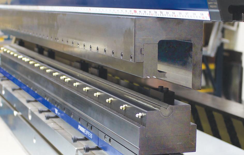
Figure 2
This rotary-style tool arrangement allows the operator to bend a flange upward, while keeping the panel in the horizontal plane.
Because they are performing a bottoming operation, wiping tools do require significant tonnage. For that reason, you rarely see wiping applications in mild steel thicker than 0.125 in. Forming tonnage calculations, in tons per foot, often involve multipliers between 250 and 300 times the material thickness. As always, check with your tooling and equipment suppliers to ensure your wiping application is within safe tonnage limits.
Despite these drawbacks, wiping tools do have significant benefits for the right application, especially if slight angular variation or sheet marking isn’t a concern. These inexpensive tools are simple, easy to maintain, and in certain situations can boost productivity significantly.
Designed with a sufficiently large cavity, the tool can handle edge flanges with several successive bends. Wiper dies also can be oriented to up-form or down-form. In a staged setup, an operator can form a positive flange in one tool set, then move over to form a negative flange in the next tool set—no flipping of the sheet required.
Like wiping tools, rotary-style tools specialize in forming edge flanges, but in a much more controlled manner. A Pac-Man-shaped cam rotates in a saddle and wraps the material around a die called an anvil. The flange needs to be at least the width of the V opening on the rotating cam (Pac-Man’s “mouth”) and the maximum flange depth is again governed by the space available in the tool cavity. And like in a wiping tool, a large cavity in a rotary tool can accommodate an edge flange with several bends (see Figure 1).
Rotary forming is usually suitable for materials up to about 0.250 in., though at that size you need a larger cam (which has a larger V opening) to handle the higher forming forces. The tool can handle thicker metal because it essentially performs a modified air forming operation, which means the forming tonnage required is usually less than half of what wiping requires.
However, rotary bending is not a true air form, where you have just three points of contact between the punch and die, and the radius forms in proportion to the die opening (not the punch nose radius). In rotary bending, the inside bend radius does not form in proportion to the width of Pac-Man’s mouth (V opening) in the rotating cam. Instead, the cam wraps the sheet onto the anvil, which governs the inside bend radius. The anvil is recessed so you can overbend a few degrees to account for springback.
You can also bend multiple angles by adjusting the stroke of the ram. The range of included angles isn’t as wide as in conventional air bending, but it is significant. A rotary tool typically can bend included angles anywhere between 75 and 135 degrees. Some tools can form open angles up to 145 degrees.
This bending method gives you the comfort and efficiency of bending a piece horizontally, with most of the workpiece staying flat during the bend cycle, and with the control and precision of conventional air forming. If a sheet from a new batch underbends slightly, you can adjust the ram position and add a few more degrees of overbend.
Such precision becomes especially valuable when forming multiple flange bends. Forming these on a press brake, you have no choice but to gauge off the previous bend. If that bend angle is a little off—as can happen with a wiping tool, as described earlier—the tolerances stack up over several bends, sometimes enough to produce a bad part.
Some specialized applications use double rotary bending systems that can help make two angles at once, often to form deep channels in sheet metal. And like their single rotary bending cousins, these double rotary tools are designed to adjust for springback and angle variation from material inconsistencies.
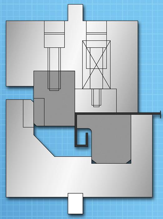
Figure 3
In a wiping operation, the punch (on left) “wipes down” the sheet against the die (on the right), which governs the inside bend radius and bend angle.
Rotary bending does require some tool maintenance, especially in a high-production operation. The saddle holding the cam needs to be greased regularly. In some high-production situations, grease fittings can be inserted on the die, so that you can quickly squeeze a little grease into the cam connection without incurring downtime between jobs.
When possible, try placing the rotary cam punch on top and the anvil die on the bottom, creating a down-bend. This helps minimize debris. When you place the rotary component on the bottom, the sheet moves down slightly during the bend cycle, requiring the operator to move with the sheet. As the cam rotates, debris from workpieces tends to fall into the rotating components, so they can require more frequent inspection and cleaning.
Still, sometimes it makes sense to use rotary tools in both the up-forming and down-forming orientation. As with the wiping tool setup, you can bend a positive flange and then move to the next tool to the negative flange, without flipping the sheet (see Figure 4). Regardless of how the tool is oriented, both the rotary punch and anvil die should be cleaned regularly to ensure they’re free of debris.
When it comes to gauging the workpiece in horizontal bending, you generally have three options. First, you can use a tool with a solid stop in the tool cavity itself. This works well when the tools are designed for specific parts, or you have specialty bends that would be difficult for the brake’s backgauge fingers to handle.
For example, say you have a large sheet with a cutout in the center, where an interior flange needs to be bent. In this case, it may be easier to simply gauge the flange edge against the stop in the tool cavity itself, instead of relying on the brake’s backgauge. The downside, of course, is that the gauge stop in the tool stays in one position, so it’s normally used for just one flange depth.
As a second option, windows can be machined in the tools themselves, so that the press brake’s backgauge fingers can enter the tool cavity and provide a gauge for the flanges. Because the machine’s adjustable backgauge has access to the part edge, you can use the rotary tool to bend multiple flange depths.
Some press brakes have backgauge fingers that are too large to fit inside the tool cavity, so in these cases, horizontal bending tools can come with spring-loaded gauging, which extends behind the tool. The brake’s gauge fingers push on the spring mechanism, which in turn moves a smaller gauge inside the tool cavity. This again gives you the ability to form multiple flange depths with one tool.
Such tools are again usually limited to edge flanges, several inches in width, but it just so happens that a lot of edge-flange work, especially in large panels, involves a lot of lifting. If using conventional tooling, the end of a long panel can travel a long arc as it whips up during the bending cycle.
Lifting large panels, even those of light-gauge material, often can require two or more operators. Sheets can kink and cause quality problems. Most important, press brake operators can become fatigued after a day supporting large sheets.
Horizontal bending tools can give them some relief. During the bending cycle, operators now need only hold such sheets steady in the horizontal plane. This can make the best operators more efficient, less fatigued, healthier, and happier. That’s a good sign of a productive shop floor.
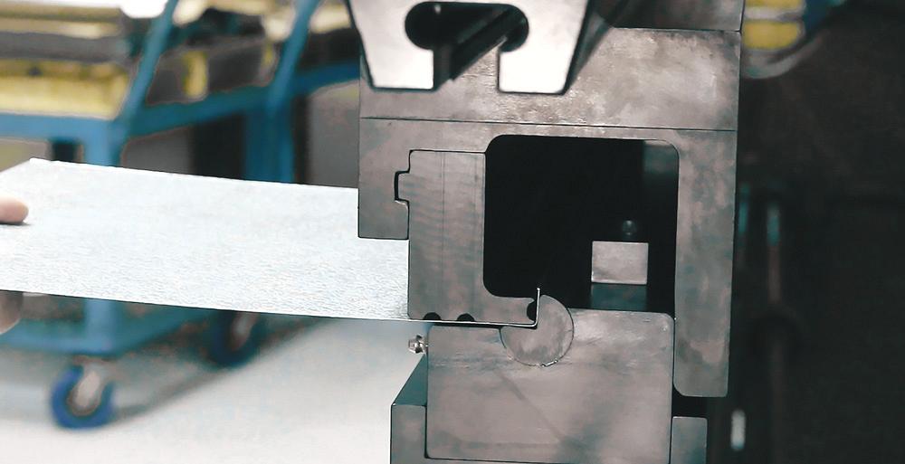
Figure 4
Rotary-style tools can be oriented for up-forming, as shown here, and down-forming, as shown in Figure 1. In a staged bending arrangement, you can create a series of positive and negative bends without flipping the sheet.

The Fabricator is North America's leading magazine for the metal forming and fabricating industry. The magazine delivers the news, technical articles, and case histories that enable fabricators to do their jobs more efficiently. The Fabricator has served the industry since 1970.
start your free subscription
Easily access valuable industry resources now with full access to the digital edition of The Fabricator.

Easily access valuable industry resources now with full access to the digital edition of The Welder.

Easily access valuable industry resources now with full access to the digital edition of The Tube and Pipe Journal.

Easily access valuable industry resources now with full access to the digital edition of The Fabricator en Español.
In this episode of The Fabricator Podcast, Caleb Chamberlain, co-founder and CEO of OSH Cut, discusses his company’s...


