


Press brake bending and the notch: A deeper dive
Even in a CAD world, it’s still good to know the basics of sheet metal layout and notching
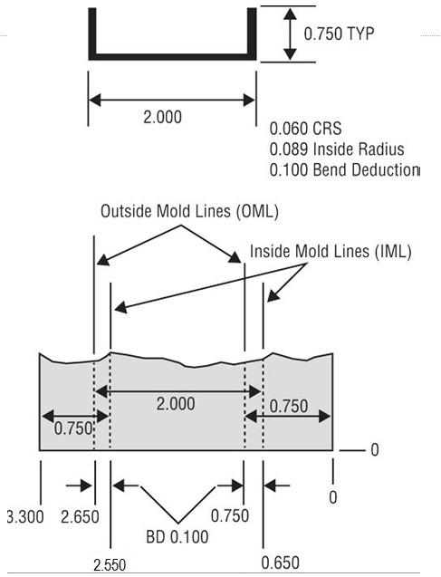
Figure 1
This simple part has two 0.750-in. flanges and an overall dimension of 2.000 in.
Building upon last month’s topic on notches, we are going to dig a little deeper into how the inside bend radius, bend deduction, and mold lines affect the quality of the products you are producing.
Just like last month, to really understand notching and its effect on the bend radius, you need to know the basics of bend deduction (BD), bend allowance (BA), and outside setback (OSSB). For more on these and other fundamentals, you can refer to the Bending Basics archive at www.thefabricator.com/author/steve-benson.
Notching may not seem to be an appropriate topic for a column on bending, but it really is. As described last month, the type of notch directly affects layout dimensions and bending order. From the press brake operator’s perspective, notching and bending have a symbiotic relationship.
For most of us, our CAD systems take care of these layout calculations. Nonetheless, manual notch layout is still used for one-off products or in prototype shops. Whichever method you use—CAD or manual—to perform this task, it is the radius and bend deduction that will make or break your part.
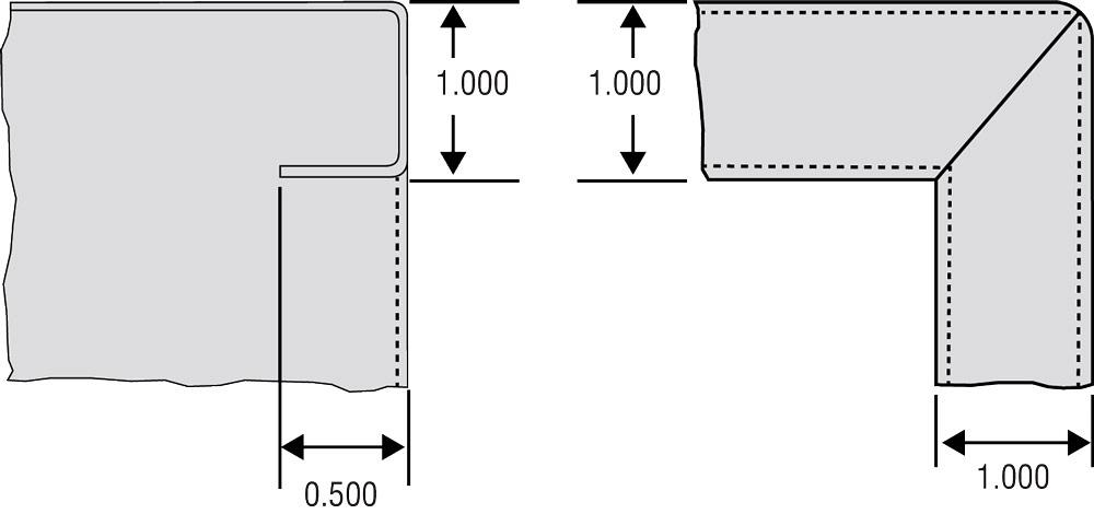
Mold Line Basics
We begin our journey with a closer look at mold lines. These are imaginary lines that when placed on the flat pattern or drawing represent the area that will be the bend radius after forming. Generally speaking, the outside mold line (OML) is the same value as the full outside dimension of the flange, and the inside mold line (IML) lies one bend deduction less.
Figure 1 shows a simple part with two 0.750-in. flanges and an overall dimension of 2.000 in. The BD in this example is 0.100, and the material is 0.060-in.-thick cold-rolled steel. The area between the IML and OML will be the bend radius after forming.
The first OML (on the right) is placed at 0.750 in., as specified by the full outside dimension of the flange. We then place the IML at one bend deduction less (0.100 in.), or at 0.650 in. We find the dimension to the second OML (on the left in the drawing) by adding the outside dimension of the overall (2.000 in.) to IML from the first bend (0.650 in.): 2.000 + 0.650 = 2.650 in.
Subtracting one full bend deduction from the second OML, we get the second IML: 2.650 – 0.1000 = 2.550 in. To that dimension we add outside flange dimension (0.750 in.) of the second bend to find the total flat blank dimension: 2.550 + 0.750 = 3.300 in.
Once you know where the mold lines go on the flat pattern, you can determine if any features you plan to add are going to lay on the radius of the bend and, therefore, distort during forming.
90 Degrees With Equal Flanges
Last month we looked at your very basic square corner notch. But how do we lay out a notch with a perpendicular flange, as shown in Figure 2? The drawing shows a side view of a part featuring two side flanges of equal length bent to 90 degrees and a single perpendicular flange also bent to 90 degrees.
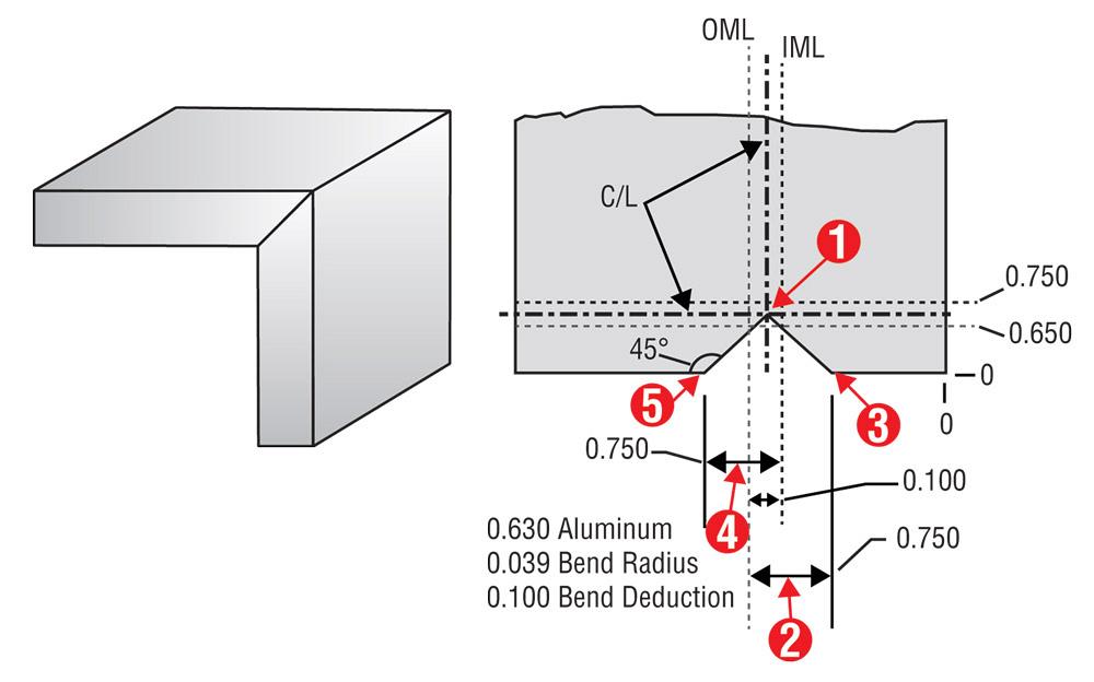
Figure 2
This simple part has two 90-degree flanges that are both 0.750 in. (The red numbers on the flat pattern correspond to the description in this article.)
Finding the OML and IML as described previously, we can develop the X-Y axes (the two bends intersecting perpendicular to each other) as they relate to the bend center lines. The center line is the center of the bend, halfway between the mold lines. The intersection of the center lines of the X and Y axes becomes the center of the notch, as illustrated in Figure 2. We’re working with aluminum with inside bend radii of 0.063 in. and BD of 0.100 in. Note the “zero-zero corner” at the bottom right, which is the starting point for all of our layout measurements. Using this data for Figure 2, the layout process goes as follows. The red numbers in the figure correspond to the numbers in parentheses below.
Find where the two bend center lines intersect (1). Follow the vertical OML down and subtract the outside flange dimension from that value. In our example, the outside flange dimension is 0.750 in. So in the X direction, we measure 0.750 in. from the vertical OML (2). That value is the coordinate of the notch corner closest to the zero-zero corner (3).
Return to the IML of the perpendicular flange and add the 0.750-in. flange dimension to that value (4). Now you have the coordinates for the notch corner farthest from zero-zero (5). You are now ready to program or lay out the part and cut the notch, while taking into account the elongation of the part during forming.
If you are using a laser or waterjet to produce these parts, the angle of the notch cut can be altered slightly to allow for springback. That is, you can modify the notch angle to account for the overbending necessary to form the part.
For example, if you know your bend is going to require clearance for 2 degrees of springback, you can use right-angle trigonometry to calculate the upper and lower corners of the notch, adding a degree’s worth of extra clearance to the bend and the mating surfaces (see Figure 3).
More Than 90 Degrees With Equal Flanges
Now let’s look at the layout of a perpendicular notch bent to a complementary angle greater than 90 degrees, as shown in Figure 4. The 0.500-in. side flanges are bent at the horizontal mold lines to 90 degrees; the bend deduction (and distance between the mold lines) is 0.100 in. Meanwhile the perpendicular bend is 120 degrees complementary (60 degrees included), with the BD of 0.250 in.
First, define the triangle at the intersection of the notch, based on what we know. As shown by the side view in Figure 4, the notch is being bent to a 60-degree-included (120-degree-complementary) angle, and we draw a triangle where the notch dimension will be. The triangle splits that 60-degree-included bend angle in half, so we know that angle C has to be 30 degrees. We also know that side c is the same dimension as the side flange: 0.500 in.
So now we have one side, the flange height and two angles, enough information to solve for the missing side using right-angle trigonometry: b = c/ tan(C); b = 0.500/ tan(30) = 0.866 in. This 0.866-in. dimension, labeled “L” on the drawing, is the adjacent side of the triangle and the required dimension needed to lay out the notch.
To find the notch location points, apply the 0.866-in. dimension to the appropriate mold line, in the appropriate direction, as shown in the flat pattern view in Figure 4.
Less Than 90 degrees With Equal Flanges
Again, we need to define a right triangle at the intersection of the notch, as shown in Figure 5. This time we’re bending to only 60 degrees complementary, or 120 degrees included. The side flanges this time are 0.750 in.
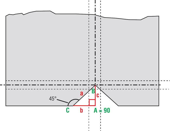
Figure 3
If you aren’t manually punching but instead cutting parts on a laser or similar blanking machine, you can change the notch angle slightly to account for springback. You can think of the notch angle as double the “B” angle of the right triangle shown here. If you know what B is, and you know dimension c (edge to bend center line), you can calculate the remaining dimensions using a variety of right-triangle trigonometry formulas. (For more on this, see www.theartofpressbrake.com.)
As before, the triangle splits the 120-degree-included angle in two, so the angle at C is 60 degrees. And we know c is the 0.750-in. flange dimension. From here we solve for our missing value: b = c/tan(C); b = 0.750 in./tan(60) = 0.433 in.
We then apply that dimension to the flat pattern. The center lines still establish the first of our locations. And from the related mold lines we either add or subtract 0.433 in., the same way we did for the 0.866 value in Figure 4.
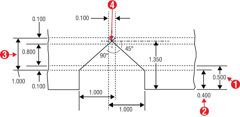
Square Corner With Equal Flanges
These are corners with two up-flanges on both axes, as shown in Figure 6. This is similar to what we have looked at so far, though with some key differences. Walking your way through this layout will require stepping through the mold lines to find where the center lines intersect at the notch.
The bend deduction for both bends is 0.100 in. The OML is the flange’s outside dimension, 0.500 in. (1). One bend deduction less is the IML, at 0.400 in. (2). To the IML we add the full outside dimension of 1.000 in. (3), which gives us the true OML location for the second bend. We then subtract half the bend deduction to find the center line: (0.400 + 1.000) – 0.50 = 1.350 in.
Find where this center line intersects with the center line of the perpendicular bend (4), and this is where your notch should go. From here you can measure the notch dimensions the same way as shown in Figure 4.
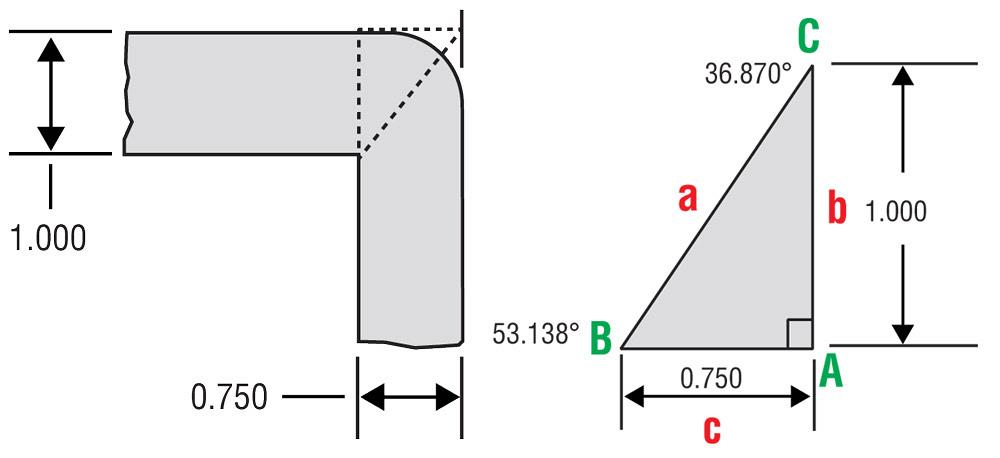
Unequal Side-flange Notching
All of the previous examples had side flanges of equal length, making the math for the notch relatively easy to calculate. But what happens when the side flanges are unequal?
The layout and the math get a little more difficult to perform, but not unreasonably so. Even here, if we follow a few simple rules, the resulting formed notch will align perfectly.
Unequal flanges create a special issue: the shifting of the center point. In essence this means the notch will tip slightly. This is necessary to ensure that the bottom corners close and meet squarely.
When creating this type of notch, the center line will shift in favor of the taller flange. This shifting or tipping of the notch allows the notch corners to meet at right angles when formed.
In Figure 7 we find a part with two flanges, the first 1 in. and a second 0.750 in., in conjunction with a single perpendicular bend. The first step is to find and define the right triangle at the intersection of the bend notches. Since we know the flange dimensions 1.000 in. and 0.750 in. (side b and side c), and angle A is 90 degrees, we can run (among many others) the following trig formula: B= tan-1(b/c); B = tan-1(1/0.750) = 53.13; C = 180 – (A + B); C = 180 – (90 + 53.130) = 36.87.
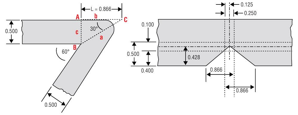
Figure 4
This shows a side view (top) and flat pattern for a notch bent to 120 degrees complementary (60 degrees included).
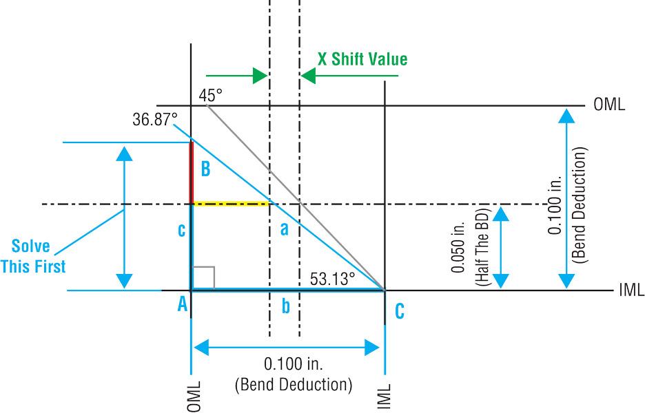
From here, we need to calculate the “X shift value,” which shows us the space we need to account for the notch shifting toward the larger flange. As shown in Figure 8, we first work with the right triangle created with the new 36.87-degree notch angle, as outlined in blue. We know that side b is the space between the perpendicular mold lines—that is, it’s the same as our BD, 0.100 in.
Because the blue right triangle is the same right triangle we defined earlier, just with smaller dimensions, we know all the angles. We know angle B is the same as our new notch angle, 36.87 degrees. Because right triangle angles add up to 180, we know angle C has to be 53.13 degrees (180 – 90 – 36.87 = 53.13). Knowing all this, we do the following, as illustrated in Figure 8:
1.Solve for side c using a right-angle trig formula such as:
c = b/tan (B)
c = 0.100/tan (36.87)v
c = 0.133
2. Subtract half the bend deduction from this value: 0.133 – 0.050 = 0.083. This is the length of the red line in Figure 8. This makes one leg (c) of a smaller right-angle triangle.
3. Solve for the yellow line (b):
b = c/tan(C)
b = 0.083/Tan (53.13)
b = 0.062 v
4. Subtract this value from half the BD, and you get the X shift value, shown in green in Figure 8: 0.062 – 0.050 = 0.012 in.
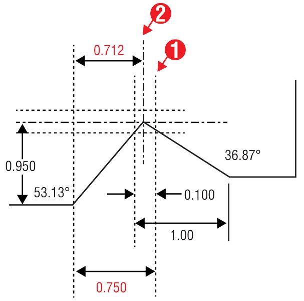
As shown in Figure 9, to find the new notch center, locate the first coordinate for the 0.750-in. flange dimension to the IML location before the shifting (1). From that first location we subtract one-half of the bend deduction (0.050) to get to 0.700, then add the shifting value of 0.012 in. to get 0.712 in. From that first notch location, subtract the 0.712 in. to find the location of the shifted center point (2).
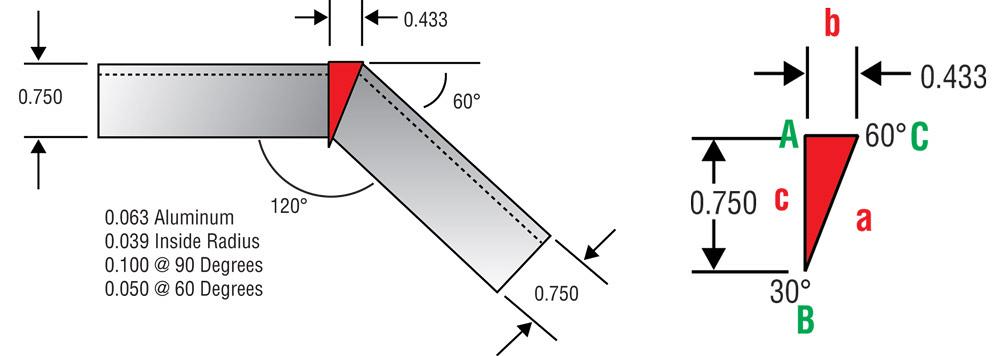
Figure 5
This shows a notch bent to 60 degrees complementary with equal side flanges.
Conclusion
You may not require this kind of precision for your products, but if you do, take a few minutes to review the topic. It goes much deeper than the few examples I have given here.
A fair amount of material on the topic is available in print and online. However, the next time you pass a used bookstore, stop in. Many times you can find wonderful works on sheet metal layout that you can sometimes get for free—because few people realize the value of what they are looking at. Save a book, save some knowledge, and build a personal library.
About the Author

About the Publication

subscribe now

The Fabricator is North America's leading magazine for the metal forming and fabricating industry. The magazine delivers the news, technical articles, and case histories that enable fabricators to do their jobs more efficiently. The Fabricator has served the industry since 1970.
start your free subscription- Stay connected from anywhere

Easily access valuable industry resources now with full access to the digital edition of The Fabricator.

Easily access valuable industry resources now with full access to the digital edition of The Welder.

Easily access valuable industry resources now with full access to the digital edition of The Tube and Pipe Journal.

Easily access valuable industry resources now with full access to the digital edition of The Fabricator en Español.
- Podcasting

In this episode of The Fabricator Podcast, Caleb Chamberlain, co-founder and CEO of OSH Cut, discusses his company’s...
- Trending Articles
1
Tips for creating sheet metal tubes with perforations

2
Supporting the metal fabricating industry through FMA

3
JM Steel triples capacity for solar energy projects at Pennsylvania facility

4
Fabricating favorite childhood memories

5
Omco Solar opens second Alabama manufacturing facility
