


Press brake gauging conundrum: Just pin it
How a simple pin can save your sanity
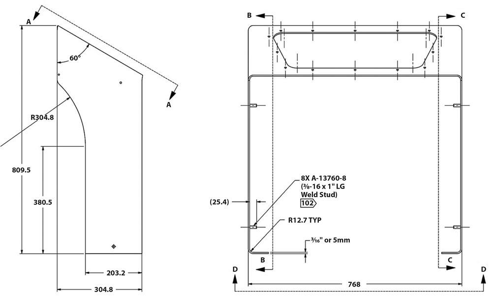
Figure 1
The side view on the left shows Section A-A, an angled bend line that presents some forming challenges.
Question: We have a very difficult part to gauge. The bends are at odd angles. That is, the bends are not square to the part, and yet the part itself still needs to be square while holding a linear tolerance that is very tight (see Figures 1 and 2). How would you go about forming this part?
Answer: Judging by the drawings, I see this part will be difficult to form. You not only have a gauging conundrum, but you also need to hold the geometry of the angled bend lines—those not parallel to the part edge, as shown in Section A-A in Figure 1. Perhaps most challenging of all, you also have to maintain the 685.8-mm dimension between the 11-mm holes, shown in Section D-D of Figure 2.
Not to fear, though. You actually have four potential ways to perform the gauging operation. All four will produce the part, though some methods are more accurate than others.
1. Custom Fixture Building
Your first and least desirable option is to build a custom fixture to gauge from. In practice, a custom fixture can help you gauge pieces very accurately, but building it can be a costly affair, especially considering you’d need both a left- and right-hand version of the fixture to complete the finished part.
Because you will be gauging from the edge, holding a feature-to-bend-line dimension will be difficult. In fact, gauging from the edge of the part is what will make the 685.8-mm dimension (see Figure 2) hard to hold. This is because all parts have some error built into them, which can’t be helped. These account for minor errors in the bend deduction, material thickness variation, and other variables.
Look closely at Section D-D in Figures 1 and 2: Where do you want the error to go? Should it go between the bend line and feature (those 11-mm holes) or between the edge and the bend line? Yes, that’s right; you want the error to go between the bend line and edge. But if you use a custom fixture, the chances are good that you will be gauging from the edge of the part, which will move the error between the bend line and the holes. That error means you will not be able to hold that 685.8-mm dimension between the holes. This of course makes this the least desirable option.
2. Side-gauging With a Single Backgauge Finger
Your second option is to gauge the first two 72.9-mm flanges (the ones with two 11-mm-diameter holes, as shown in Figure 2) using your standard backgauge stops to locate the bend line. Those first two bends are parallel to the part edge; however, the second set of bends will require an additional set of side gauges. These side gauges need to be angled relative to the perpendicular edge and the first set of flanges, as called on the print—60 degrees included, in Figure 1, Section A-A. This means you need to use a side gauge that’s 30 degrees from perpendicular with the die, and it means right and left gauges will be required.
As an aside, the corner edge of a bend can convex (bulge out), causing a change in the gauging angle.
By gauging from the part edge, you will hold the part edge-to-bend-line dimension, as called on the print, but this is a noncritical dimension. As noted previously, any error will manifest itself in the feature-to-bend-line dimension. (Note that the bend-line-to-feature dimension isn’t even called on the print, yet it’s extremely important for forming the part accurately.)
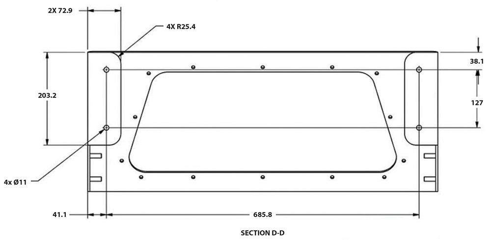
Figure 2
The best gauging solution would be to use a pin-gauging method, inserting gauging pins in the 11-mm-diameter holes in the 72.9-mm-wide flange.
The critical dimension is that 685.8-mm measurement between the 11-mm-diameter holes in the flanges (Section D-D in the figures). This is worth repeating: To hold that 685.8-mm dimension after forming, the error, or “floated” dimension, in the two base flanges needs to be placed between the edge and the bend line.
Even if you manage to form the first set of flanges correctly, how do you gauge the second set—that is, the flanges not perpendicular to the part edge? You could side-gauge the part with a single stop, but it would require installing three sets of tooling: one for the first two bends plus two more, a right- and left-hand setup for the second set of bends.
Under the best of conditions, your consistency will be all over the map, especially if the error was not properly dealt with in the first flanges by keeping the error between the edge and feature. In fact, if you use either one of these first two gauging methods, the error will no doubt end up right where you don’t want it to be.3. Laser Stitching
Laser stitching is the concept of leaving extra material on the workpiece, like small shaker tabs taken from the skeleton or other throwaway pieces of the mother sheet. These extra pieces that remain laser-stitched to the workpiece can be shaped in such a manner as to provide gauging surfaces that are parallel to the bend line. This makes curved surfaces, odd shapes, and angled bend lines easy to gauge.
This is the best option in many cases, but not for this particular piece. That’s because the angled bend line is deep into the part, where it cannot be completed first. Using the laser-stitching method, you theoretically could perform these two internal bends in the necessary forming order, but it would take quite a bit of creativity from both the programmer and the machine operator.
4. Pin Gauging
Pin gauging uses features already present in the workpiece to gauge the bends. This type of gauging will hold the dimension from feature to bend line as required in the first bends. In fact, pin gauging is the only real answer that corrects for both the dimensional challenges (keeping the error between the bend line and edge) and the gauging issues presented by the angled bend lines.
You can make a pin gauge using a pin, drill rod, PEM hardware, or even a half-shear (a punched hole in which the slug is pushed only partway out of the sheet). Any of these can create an edge to gauge against. In this case, you would need to make a gauge that fits easily into the 11-mm holes and the 72.9-mm flanges.
The pin gauge will hold the dimension from the holes to the bend line, remove the error, and place it where you want it: the noncritical edge-to-hole dimension.
Next comes the angled bend line. I would pin-gauge out of the 9.9-mm and the 6.1-mm holes. Make sure both necessary pin gauges fit easily into the 6.1-mm feature. This one will be tricky as the two holes are not parallel to the tapered bend line, as shown in , Sections B-B and C-C.
You can mount pin gauges to the regular stop fingers. Once the gauges are mounted and adjusted, simply place the part in between the punch and die, over the pins, gauging to the back.

Figure 3
Make sure both necessary pin gauges fit easily into the 6.1-mm feature. This one will be tricky as the two holes are not parallel to the tapered bend line, as shown in Sections B-B and C-C.
If your backgauging system has independently adjustable stops, you can program the stop locations into the controller. If your press’s backgauge is a little more basic, you will need to mount a fixtured version of the pin gauge to the backgauge, and you’ll need separate right- and left-hand fixtures because of the feature sizes and locations relative to the bend line.
By using pin gauging, you should have no problem forming while easily holding the tolerance, if your bend deductions were calculated correctly.
The Final Bend
This part has one last challenge: the last bend. You need to physically remove a section, a tool, or both to create a hole for the previously formed flange to pass through. To do this, you will need to use a window or tunnel punch. You can make such a punch by using spacer blocks between the ram and tool.
There is more to know about using a window punch than you might imagine. You need to consider tonnage loads, forming methods, and bend deduction issues. The punch is by its very nature a weak tool as compared to most, and it is subjected to a
To compensate for this deflection, you need to air-form to minimize your tonnage load. You also want to use the largest bottom die possible; a wide opening relative to material thickness reduces the tonnage.
To determine the largest die opening, work backward from the maximum allowable inside radius, as defined by the print, using the 20 percent rule to determine the floated inside radius. The rule is named after the percentage used for stainless steel, but the baseline material is 60-KSI cold-rolled steel, which forms a radius that’s about 16 percent of the die opening. (For more on this, see “How the inside bend radius forms,” archived on thefabricator.com.)
After you select your maximum die opening, select a punch nose radius as close as possible to the naturally floated inside radius; do not use a punch nose radius that is larger, as the bend will tend to take on that larger radius and wreak havoc on your calculated bend deduction. (My upcoming textbook, to be published soon by the Fabricators & Manufacturers Association International®, has an entire chapter on this subject.)
This kind of part requires critical thinking, and not only about how to gauge each bend. Where do you want the error to be located? What are the effects of putting the error in a specific place (e.g., in the edge-to-feature dimension) as it relates to holding the part to print and holding dimensional consistency from part to part?
And sometimes the answer is as simple as a pin.
Steve Benson is a member and former chair of the Precision Sheet Metal Technology Council of the Fabricators & Manufacturers Association International®. He is the president of ASMA LLC, steve@theartofpressbrake.com. Benson also conducts FMA’s Precision Press Brake Certificate Program, which is held at locations across the country. For more information, visit www.fmanet.org/training, or call 888-394-4362. For more information on bending, check out Benson’s book, theArtofPressBrake: the Digital Handbook for Precision Sheet Metal Fabrication, ©2014, available at www.theartofpressbrake.com. Steve Benson’s latest book on press brake bending, published by FMA, will be available soon.About the Author

About the Publication

subscribe now

The Fabricator is North America's leading magazine for the metal forming and fabricating industry. The magazine delivers the news, technical articles, and case histories that enable fabricators to do their jobs more efficiently. The Fabricator has served the industry since 1970.
start your free subscription- Stay connected from anywhere

Easily access valuable industry resources now with full access to the digital edition of The Fabricator.

Easily access valuable industry resources now with full access to the digital edition of The Welder.

Easily access valuable industry resources now with full access to the digital edition of The Tube and Pipe Journal.

Easily access valuable industry resources now with full access to the digital edition of The Fabricator en Español.
- Podcasting

Seth Feldman of Iowa-based Wertzbaugher Services joins The Fabricator Podcast to offer his take as a Gen Zer...


