


Press brake strategies: Boosting forming throughput
Real improvement comes after good measurement
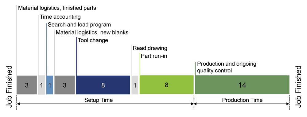
Figure 1
This time study shows a typical bending cycle at a custom fabricator, shown in minutes. Note that production time makes up less than half of the overall cycle. (Note: “Time accounting” represents operator breaks and other miscellaneous tasks not otherwise accounted for.)
Editor’s Note: This article is adapted from Vincent Iozzo, “Boosting the Bends Per Hour: Tips and Technologies for Reducing Press Brake Setup Time,” presented at FABTECH®, Nov. 16-18, 2016, Las Vegas.
Bending is at the heart of metal fabrication. How well jobs flow through the press brake department often dictates how smoothly jobs flow through the entire shop, from raw stock to the shipping dock. Inefficiencies at the brake can ripple through the entire operation.
What causes these inefficiencies? That’s difficult to answer without first actually measuring how long it really takes to process jobs at the press brake. After all, it’s difficult to make something better on a hunch. Put another way, if you don’t measure it, you can’t improve it.
Measuring It Right
How you measure processing time at the press brake matters. It’s important to identify when a “bending job” starts and stops. A bending job really isn’t finished unless the next operation can do something with it. Moreover, a bending job doesn’t start when the operator runs the first test piece, or even when he or she calls up the program. It starts with material retrieval—that is, staging the cut blanks so the forming job can begin.
Measuring this way helps put bending in perspective. The idea is to shorten overall manufacturing time. An operation may group like jobs together to make setup easier, but can the downstream operation do something with those parts once they’re formed?
When you look at the time study in Figure 1, which represents a typical operation, it becomes abundantly clear: Actual production time sometimes can be less than half of the overall bending process. The rest is setup time. Shorten that setup time, and you boost the number of parts you can bend per hour. Make the bending operation flexible, and you won’t need to consider scheduling like jobs together just to save a little on setup. The goal is to manufacture the right parts so that they’re ready at the right time for the next operation.
Figure 1 starts with “material logistics for finished parts.” This is when operators or staging personnel move the finished parts from the previous job out of the press brake area and stage them to the next step. Alternatively, this could be at the end, after “production time.” It doesn’t really matter where this time is, as long as it’s accounted for. It’s difficult for the operator to start a new job if he has a pile of formed parts near the machine; and again, unless those parts are staged and ready for the next operation, the bending process really isn’t finished.
Time for material logistics, both of finished parts and new blanks, can be streamlined by having a material handler stage, retrieve, and deliver new blanks and finished parts. The time study in Figure 1 already assumes that material will be staged and finished parts will be delivered by a dedicated material handler. But it still requires several minutes to clear the work area of formed parts and place fresh blanks into position.
Next comes “search and load the program.” A fabricator can shorten this time with simple bar codes on move tickets or job packets. A job arrives at the station, the operator scans the bar code, and the program loads.
Note that this time study assumes a fabricator is programming its press brakes offline, showing a process simulation with the shop’s available tools in a model of the actual press brake the operator will use. Programming on the floor obviously adds setup time, and most significant, it also makes unforeseen troubles more likely. For instance, the job may be impossible to bend, perhaps because the part collides with tooling and gauging as it’s being formed, or the tooling needed to form the part isn’t available, or the blank dimensions are incorrect.
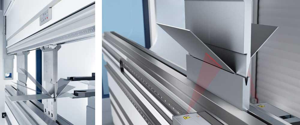
Figure 2
Automatic angle measurement and correction can help minimize part run-in time. A tactile measurement system is shown on the left, and a laser-based measurement system is shown on the right.
To fix the problem, the operator may go back and forth with engineering, or he may just try to “make it work” with the tooling he has. This can lead to problems downstream and create an undocumented process, which can make training and process standardization even more difficult. Just “making it work” is never ideal.
Offline bend programming is becoming more and more common. In the not-too-distant future, it’s likely to become standard, particularly in high-product-mix situations. For this reason, the time study in Figure 1 does not incorporate programming at the machine.
It also assumes that the operator is working with a modern press brake controller—hence, it takes a minute (or less) to read the print and verify the program is correct. The control provides the operator with a 3-D visualization of the process, so the operator need not spend a lot of time studying the drawing and work instructions to determine the bend sequence.
The time study does, however, incorporate altering the program as an element of the “part run-in.” This time mainly involves first-article quality checks and adjustments the operator makes because of material variation, particularly in material thickness. The operator measures the thickness of the cut blanks in front of him, then enters that new material thickness into the control, which (at least ideally) makes the appropriate adjustments. After that the operator bends another test part and measures it with a caliper and protractor. And he may have to take the part to the quality department, if the job requires it. All this can eat up time, which is why “part run-in,” or part tryout, consumes such a large portion of the time study.
It’s also where fabricators can eliminate significant inefficiencies. It’s always ideal to “engineer out” a problem, and with prolonged part run-ins, this sometimes can involve scrutinizing the material and how it’s presented to the press brake operator. The more consistent material quality is, the less time an operator will need to spend tweaking setups to accommodate for material variation.
Cutting strategies play a role here too. Depending on the material and job requirements, a change in grain direction (that is, bending with or against the grain) may require a bending adjustment, which takes time and adds variability to an already complex bending process. When practical, the nesting programmer should try to keep the grain direction on identical parts uniform.
Shortening the part run-in also can involve some low-hanging fruit. What if an operator spends time searching for calipers and protractors or must walk across the floor to retrieve those measurement tools? Here a fabricator can implement some basic 5S, such as placing tools on shadow boards, to ensure every press brake has the properly calibrated tools necessary for the operator to complete his job. An operator also needs something to write with to record measurements on the job packet.
Recording those measurements on test parts tends to be a manual job. In between a laptop or computer terminal where the operator clocks in and out of the job and an advanced CNC on the press brake itself, an operator still puts pencil to paper to record measurements during part run-in and for periodic quality checks.
To eliminate this task, automation and digital technologies have played key roles. Some operations now use digital measuring devices that connect directly to the CNC. An operator runs a test part; measures it; and the resulting data feeds directly into the control, which then has the information it needs to make the appropriate adjustments.
This still involves forming a test part and manually measuring it, of course. To streamline operations further, a fabricator can invest in automatic bend angle correction (see Figure 2). These technologies come in various forms, incorporated into the press brake and tooling, but they all aim to measure the bend angle in-process and make corrections. The desired result: The first test piece should be a good part.
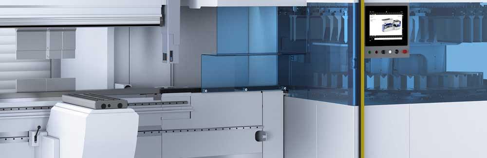
Figure 3
This automatic tool changer can be added to certain manual press brake models. A conveying system pushes and pulls tools into designated slots.
The remaining piece of the bending process puzzle involves the actual tool change. Low-hanging fruit here includes basic tool organization and ensuring every press brake has the tooling it needs at the right time. Some shops have designed rolling racks of tooling that incorporate errorproof storage. Punches and die segments fit into clearly labeled slots, and they fit only certain ways. If an operator attempts to place a tool into the wrong slot, it simply won’t fit.
More and more fabricators are removing manual tool change entirely with automation. Today’s tool-change automation comes in various forms, be it specialized press brakes or as an add-on to certain manual press brake models that have the open height needed to work with the tool-change automation (see Figure 3). Such automation allows tool change to occur simultaneously as the program is loaded, formed parts from the previous job are removed, and blanks for the next job are staged for production.
Not About Number of Strokes
Improving bending throughput isn’t about measuring the number of times a machine cycles over a certain period. If “maximum strokes” were the goal, an operator would group identical or similar jobs together, produce extra to save on setup, and build excessive work-in-process inventory that operations downstream don’t need.
Instead, it’s about measuring the time between retrieving blanks to delivering formed parts to the next operation. When analyzing the time, a fabricator should pay special attention to the part run-in, or tryout, time. This alone could have implications upstream, including in laser cutting and punching. In a quest for maximum material utilization, a programmer nests as many parts as possible, facing them every which way on a sheet. He also may use remnants from a previous batch. This strategy can work in many situations. But when bend angle tolerances are critical, it can present hurdles and prolong part run-in time significantly.
Nesting strategically, with identical parts cut with the same grain direction, or keeping critical parts in the same sheet or batch of sheets, can improve matters. So can investing in automatic bend angle measurement (which adds only a small fraction of a second per bend) and correction. The investment could also give programmers more flexibility when nesting parts.
Which methods and technologies should a fabricator consider to boost bending throughput? This depends on the part mix, volume, and the nature of its bending operation. The key again is to measure what actually takes place at the press brake. Fabricators then can choose the best options that fit their operation (see Figure 4).
Whatever option fabricators do choose, their goal should be the same: An operator should spend most of his time doing value-added activities; that is, actually making quality parts that don’t sit as excess WIP, but flow quickly to the next operation.
Vincent Iozzo is TruBend product manager, TRUMPF Inc., 860-255-6000, www.us.trumpf.com. Images courtesy of TRUMPF Inc.
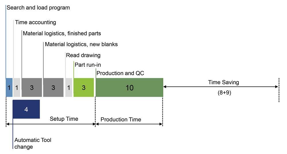
Figure 4
This is a time study after process improvements. Tool change occurs automatically and simultaneously with other setup tasks, and part run-in and production are streamlined, thanks to general process improvement as well as automatic angle measurement and correction.
About the Publication
subscribe now

The Fabricator is North America's leading magazine for the metal forming and fabricating industry. The magazine delivers the news, technical articles, and case histories that enable fabricators to do their jobs more efficiently. The Fabricator has served the industry since 1970.
start your free subscription- Stay connected from anywhere

Easily access valuable industry resources now with full access to the digital edition of The Fabricator.

Easily access valuable industry resources now with full access to the digital edition of The Welder.

Easily access valuable industry resources now with full access to the digital edition of The Tube and Pipe Journal.

Easily access valuable industry resources now with full access to the digital edition of The Fabricator en Español.
- Podcasting

In this episode of The Fabricator Podcast, Caleb Chamberlain, co-founder and CEO of OSH Cut, discusses his company’s...
- Trending Articles
1
Tips for creating sheet metal tubes with perforations

2
Are two heads better than one in fiber laser cutting?

3
Supporting the metal fabricating industry through FMA

4
JM Steel triples capacity for solar energy projects at Pennsylvania facility

5
Omco Solar opens second Alabama manufacturing facility
