


Account manager-press automation specialist
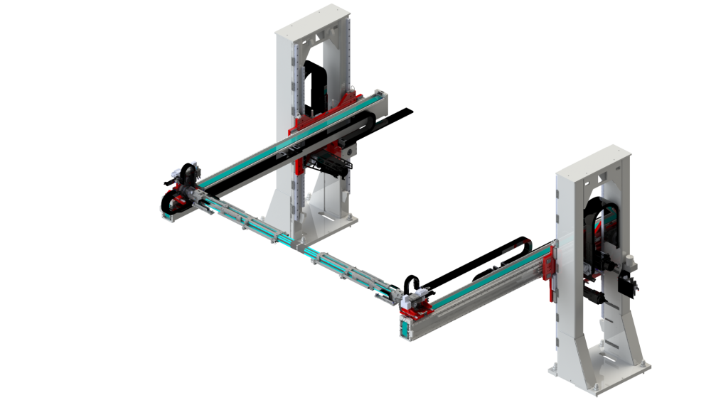
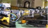
An automotive OEM installed an automated tandem line comprising five JIER press lines and a Güdel roboBeam crossbar transfer system for a direct parts transfer from press to press without an intermediate or orientation station. All of the feeders’ servo motions are linked for safety reasons to parallel operating encoders, which are always electronically synchronized to the angles of the press.
When you begin to look at a program to produce the best-quality automotive components at the highest yield rates—and throw a new material into the mix—there are a plethora of details to consider that will impact the end deliverable.
If an OEM or tier stamper wants to install an automated system to stamp its large automotive components, it must first consider all the variables such as general press configuration, press stroke length, die space opening, interference points, speed, tonnage and energy required, and scrap removal.
Tandem or Transfer. The OEM or tier stamper must first choose the general press configuration, such as a transfer press or press-to-press line.
A transfer press requires all the components to be nested in the die before cycling the press. In a tandem line, the press can cycle once the individual component is nested in the die.
In a tandem line, the presses are synchronized by a variable press shift--typically 60 degrees from each other so that press 1 will reach bottom dead center first, then press 2 will reach bottom dead center 60 degrees later, and so forth. The press center-to-center distance should be as short as possible while still allowing press repairs and maintenance. This serves as a baseline for the press placement and all other component placement.
Press Stroke Length, Die Space Opening. The press stroke length and die space opening need to be big enough to allow the components to be loaded into the dies with stability. In most cases, that requires transfer automation with two arms, as well as a wide opening for the left-to-right die space.
If a single-arm transfer is used, such as a robot, the automation will cost less, including the cost for the left-to-right press opening, because it will be smaller, but the trade-off is a less stable component because it may need time to settle and stop bouncing before being placed into the die. Full control of the component during the transfer from die to die, under acceleration, deceleration, and G forces, becomes critical.
Speed, Tonnage, Energy. The required press speed, tonnage, and energy need to be enough to produce at the required rate, and the slide motion, such as a standard eccentric drive, link drive, or a servo-mechanical press, needs to be considered. All other variable slide motions and various interference curves that come into play to accommodate the optimal slide interference/displacement curve must be considered as well.
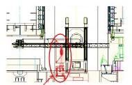
Interference Points. A review of automation integration into a press configuration should include looking at potential interference points, such as gib drip trays, oil return lines between the uprights, slide tracked vehicle tracks, control switch brackets, air automation valve connections, and bed-mounted equipment such as bolster clamps. If interference is encountered, the OEM or stamper needs to design around the interference or relocate it to permit the required clearance using a simulation tool.

The OEM or stamper runs a part’s acceleration, deceleration, part positioning, and G force inputs through the press line simulation program.
Scrap Removal. In stamping operations, scrap removal often is an afterthought. It’s best to design ahead. Scrap shedding, both through the bolster and bed, as well as scrap doors on the front and back of the press are must-have design features.
Once all of those considerations are accounted for in the planning, the die and automation tooling can begin to be placed into the press production system virtually and, ultimately, physically to validate.
Sizing Bolster, Window, Shut Height. The physical size of the dies and any add-on nitrogen cylinders, manifold, die wedges, air automation valves, and limit switches will define the physical size of the bolster, press window openings, shut height, and any other potential interference. All these details need to be addressed so that pre-stage tooling can be mounted on moving bolsters. The same can be said for separate tooling carts, if they are part of the press production system.
Drive Control. Another important consideration for the press system configuration is the main drive control. This system must have a very robust design because it will need to last the life of the press. It will be heavily tasked during press startup, launch, and new die tryout; the main drive is turned on and off many times during these steps.
Die Cushion. A decision must be made on whether to use a die cushion. There are many cushion configurations, including preacceleration, postlift, distance of resistance, and number of resistance points. Cost is a consideration as well.
Leadoff Press Tonnage. The final considerations center on the tonnage of the leadoff press. It is likely that it will need to have a higher tonnage capacity than the following presses, as a great amount of work is done in the first press. Normally, the part is drawn in the leadoff press, even if a cushion is not used and nitrogen is used instead.
The automation end effectors for picking up the blanks and downstream components are almost exclusively vacuum cups. In later generations of the automation, grippers have been added. The maximum single part size, right to left, is 4,160 mm, with the minimum being 1,145 mm. In the front-to-back direction, the maximum single part size is 2,090 mm, with the minimum being 600 mm.
To run double unattached parts, the right-to-left maximum is 1,930 mm and the minimum is 965 mm. In the front-to-back direction, the maximum is 2,090 mm and the minimum 600 mm. The weight limitation of a single blank is 60 kg, and of course a double unattached blank is 30 kg each.
The material thickness of the designed steel parts needs to be within the range of 0.4 to 3.0 mm and for aluminum, 0.75 to 4 mm.
All axes in a crossbar transfer are fully programmable for maximum flexibility.
For any specific part, the acceleration, deceleration, part positioning, and G forces are all calculated inputs that the OEM or stamper runs through the press line simulation program. These inputs are then entered into the part recipe that commands the motion path of the automation.
An automotive OEM studied how to stamp its automotive body panels, such as hoods, doors, fenders, body sides, and many of the corresponding inner components. The parts were to be formed from both aluminum and steel.
Beginning with the general press configuration for the body panels, the automaker chose to use a tandem line in the belief that this would be incrementally faster than a transfer press.
The company uses an NC cushion in the first press of the tandem line, and placement of the component into and out of the die are timed according to the movement of the cushion and presentation of the component into the pickup position for the exit automation.
The OEM uses a Güdel roboBeam automation system, which is a crossbar transfer system for a direct parts transfer from press to press without an intermediate or orientation station. All of the feeders’ servo motions are linked for safety reasons to parallel operating encoders, which are always electronically synchronized to the angles of the press.
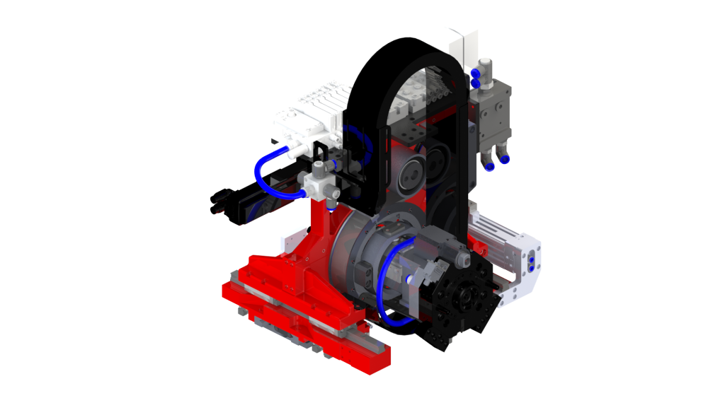
The concept of the system comprises a combination of linear motion technology and rotation units between which the crossbar is located. When the part is swiveled directly at the crossbar, a movement curve adapted to the die’s contours can be implemented. Because only a single transfer is required between the two presses, only one tooling set is required to handle the parts.
The crossbar transfer has a simple and rigid design, a large working range, and is highly compact in the die area. All axes are fully programmable for maximum flexibility. It is designed for use with mechanical link, eccentric, and servo presses.
The beam is driven by a rack-and-pinion unit and guided by two linear guides on the Z and YB axes. The movement of the carriage is achieved with a belt that is mounted and driven on the beam. This allows for independent movement of the beam and the carriage on the Y axis.
On one side of the roboBeam, two linear guides are mounted on the crossbar shuttle, functioning as a floating bearing for the crossbar.
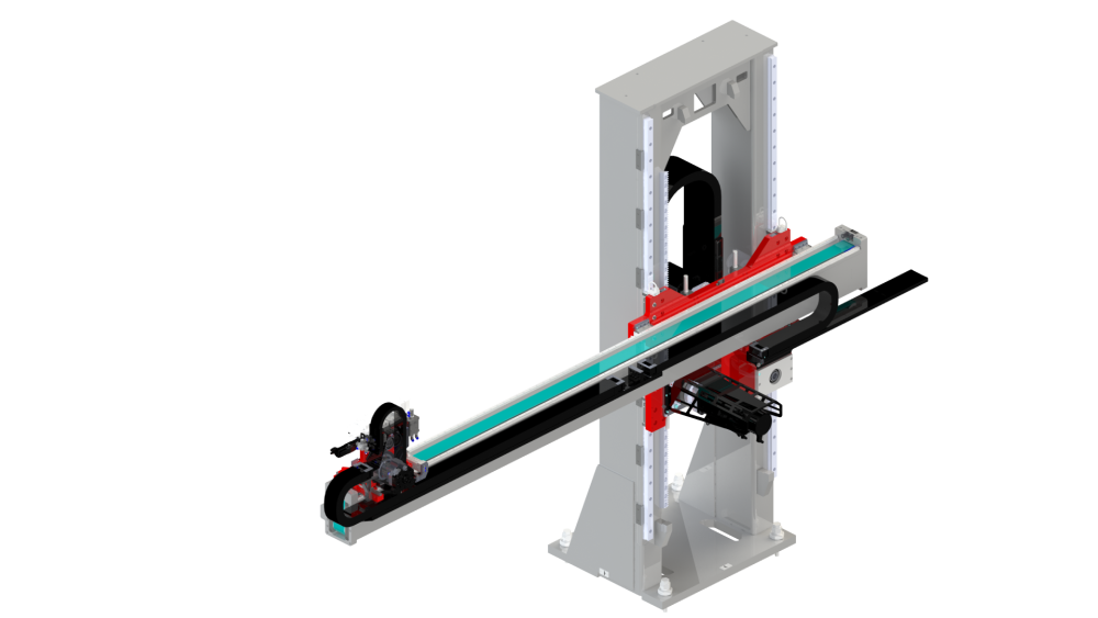
A rack-and-pinion unit drives the crossbar beam and is guided by two linear guides on the Z and YB axes.
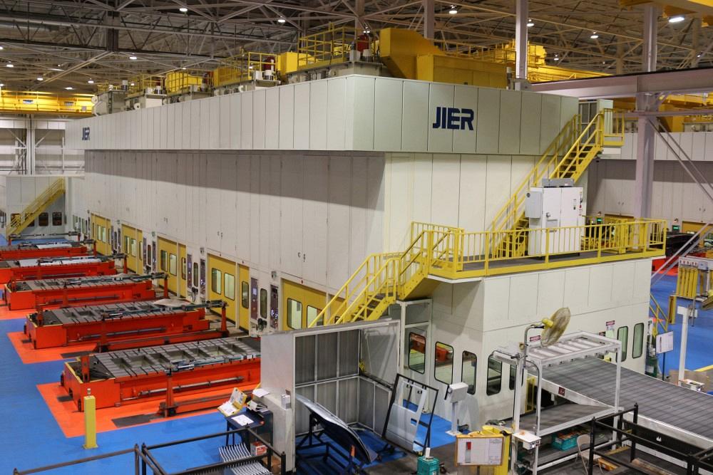
In coordination with the tandem line installation, the OEM made an initial purchase of five JIER press lines, which are installed in the Midwest at two different plants. It then purchased four additional lines once the initial lines were fully functioning and proved out. These lines are installed at various other OEM facilities in the U.S., with the customer’s most critical products being produced in those lines.
The average cycle rates achieved are 12 to 15 SPM--a new benchmark for the customer’s production plants, especially for aluminum stamping. Enhancements and redesigns were made to the automation from lessons learned, and one press line was redesigned to accommodate a lower ceiling height at an existing plant.
When challenged with a high-profile product launch, new quality and material standards, and new benchmark requirements, the OEM required an entire systems approach to successfully complete the scope of the project.
Tom Sabula is sales manager for JIER North America, 14975 Cleat St., Plymouth, MI 48170, 734-404-6683, sabula_thomas@jier-na.com, www.jier-na.com. Mark Versteegden is account manager-press automation specialist for Güdel Inc., 4881 Runway Blvd., Ann Arbor, MI 48108, 734-214-0000, mark.versteegden@us.gudel.com, www.gudel.com/us.


The Fabricator is North America's leading magazine for the metal forming and fabricating industry. The magazine delivers the news, technical articles, and case histories that enable fabricators to do their jobs more efficiently. The Fabricator has served the industry since 1970.
start your free subscription
Easily access valuable industry resources now with full access to the digital edition of The Fabricator.

Easily access valuable industry resources now with full access to the digital edition of The Welder.

Easily access valuable industry resources now with full access to the digital edition of The Tube and Pipe Journal.

Easily access valuable industry resources now with full access to the digital edition of The Fabricator en Español.
In this episode of The Fabricator Podcast, Caleb Chamberlain, co-founder and CEO of OSH Cut, discusses his company’s...


