


R&D Update: Examining edge cracking in hole flanging of AHSS, Part IIII
Part III: The effects of punch speed, material, and tool wear

Effects of Punch Speed and Sheet Material
Experiments were conducted at the Center for Precision Forming (CPF) at The Ohio State University using different sheet materials (low-carbon steel, high-strength steel, aluminum, and copper), punch-die clearances of 3 percent to 25 percent of sheet thickness, and punch speeds of 0.5 feet per second to 12 FPS. Results showed that punch speeds higher than 6 FPS could improve the edge quality, resulting in a larger shear zone, smaller burr, smaller rollover, and smaller depth of crack penetration.
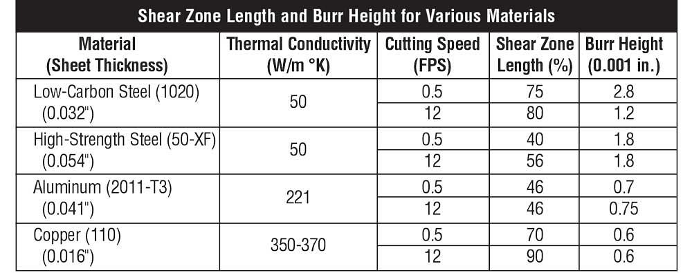
It also was found that the edge quality improvements depends on the sheet material. The dimensions of sheared edges in blanking of various sheet materials at low and high speeds are shown in Figure 1 .
Differences in part edge geometries are more distinct for steels than for copper and aluminum. Because copper and aluminum have much higher thermal conductivity than steel, heat generated when blanking these materials dissipates much more quickly. Temperature rise at high punch speeds is smaller than that encountered in blanking steel. Thus, the edge geometries obtained in blanking copper and aluminum are similar at low and high punch speeds. The part edge quality is more sensitive to punch-die clearance than to punch speed and sheet material.
If FE modeling of blanking is to take into account the effect of punch speed, the material properties must be available at high strain rates and temperatures. Preliminary simulations indicated that with a cognitional blanking speed of 0.5 FPS, the strain rate can go up to 2,100 s-1, while the temperature near the sheared edge may be as high as 250 degrees Celsius. Strain rates and temperatures obtained in high-speed blanking could be even higher.
Effect of Tool Wear
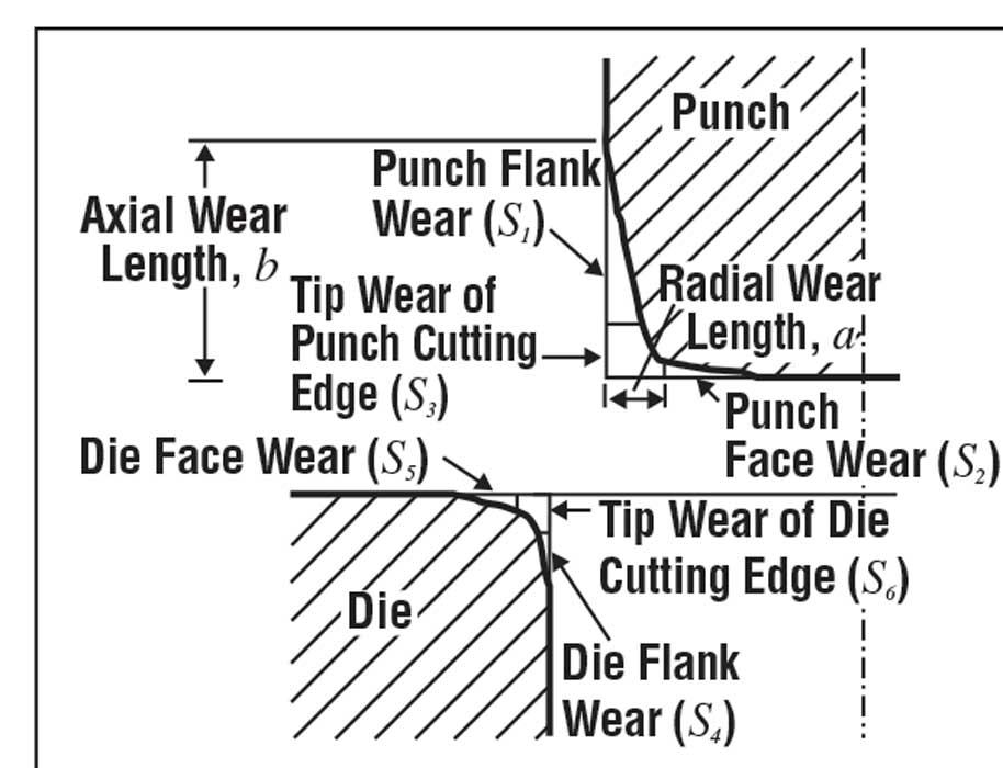
In addition to process parameters, tool wear can change the actual punch-die clearance and the tool edge geometry. This might lead to inconsistency in the part edge quality. Figure 2 shows the schematic of the worn blanking tool.
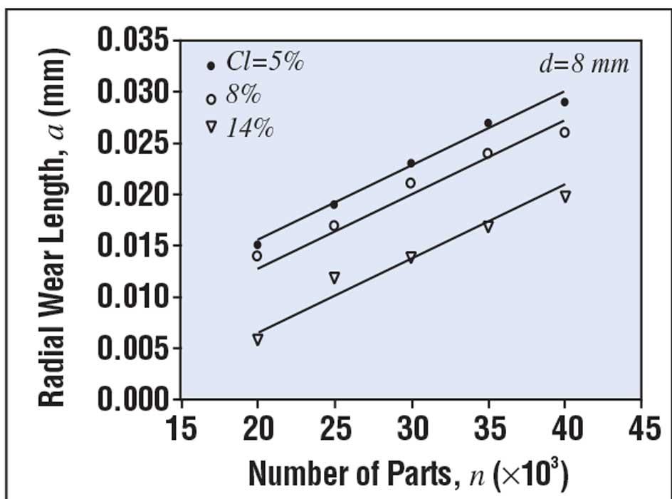
The results given in Figure 3 show that the radial wear length on the punch ( a ) can increase up to 0.03 millimeter (3 percent of the sheet thickness= 1 mm) when blanking 40,000 stainless steel sheets (AISI 304) using 5 percent punch-die clearance. Thus, the punch-die clearance increases from 5 percent to approximately 8 percent after blanking 40,000 parts.
Figure 3 also shows that a smaller punch-die clearance causes more tool wear because the deformation is highly localized, generating high stresses and high temperatures. This condition accelerates tool wear. Experimental results show that when the tool is worn out, the rollover, the burr height, and the depth of crack penetration of the sheared edge increase when using a small punch-die clearance of 5 percent. However, these values, which characterize the shape of the blanked edge, decrease when using a large clearance of 14 percent.
About the Publication

subscribe now

The Fabricator is North America's leading magazine for the metal forming and fabricating industry. The magazine delivers the news, technical articles, and case histories that enable fabricators to do their jobs more efficiently. The Fabricator has served the industry since 1970.
start your free subscription- Stay connected from anywhere

Easily access valuable industry resources now with full access to the digital edition of The Fabricator.

Easily access valuable industry resources now with full access to the digital edition of The Welder.

Easily access valuable industry resources now with full access to the digital edition of The Tube and Pipe Journal.

Easily access valuable industry resources now with full access to the digital edition of The Fabricator en Español.
- Podcasting

In this episode of The Fabricator Podcast, Caleb Chamberlain, co-founder and CEO of OSH Cut, discusses his company’s...
- Trending Articles
1
Tips for creating sheet metal tubes with perforations

2
JM Steel triples capacity for solar energy projects at Pennsylvania facility

3
Are two heads better than one in fiber laser cutting?

4
Supporting the metal fabricating industry through FMA

5
Omco Solar opens second Alabama manufacturing facility
