


R&D Update: Processes for hydroforming sheet metal, Part II
Part II: Sheet hydroforming with a punch

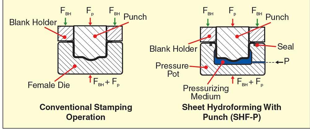
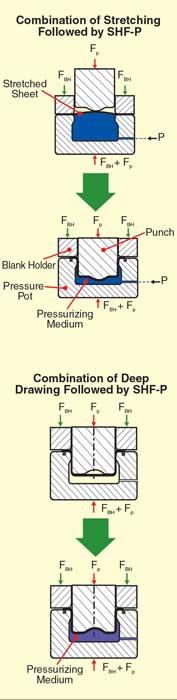
In SHF-P friction at the punch sheet interface prevents the deforming sheet from sliding over the punch surface. Thus, the stretching that occurs in conventional deep drawing is reduced or eliminated, resulting in a more uniform wall thickness and increased deep drawability. In this way, SHF-P can reduce the number of stamping operations commonly required in forming complex parts. Figure 2 show how SHF-P is combined with regular stamping to form parts with protrusions.
SHF-P, Conventional Stamping Differences
Compared with conventional stamping, SHF-P.
- Eliminates the need for a female die, thus lowering tools costs.
- Often allows forming of complex parts in one operation, thereby reducing the number of required die sets and operations.
- Requires a longer cycle time per operation— about 60 to 80 seconds versus a few seconds in conventional stamping.
SHF-P is practical for producing parts in relatively low production quantities. For example, several outer panels of General Motors’ new model Solstice® are produced by SHF-P in Amino’s plant in St. Thomas, Ont., because the anticipated volume for this car is 20,000 to 30,000 until per year.
SHF-P Press
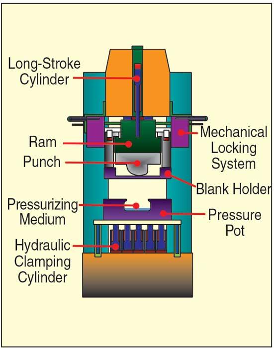
Several press manufactures, such as Schuler, Amino, and Schnupp, build presses for SHF-P with short cycle times (see Figure 3 ). on these presses, the top die is moved up and down using a long-stroke cylinder that requires a small volume of hydraulic fluid at low pressure. The ram is indexed at the bottom dead center position using mechanical locks, which eliminate the need for a high-pressure hydraulic system on the top-die.
Short-stroke hydraulic clamping cylinders mounted in the press bed are activated during SHF-P to apply the press force required to counteract the force generated by the pot pressure.
Tool Design for SHF-P
The tool design concept for SHF-P is similar to that for regular stamping. The punch and blank holder are specifically designed for the part shape, while the pressure pot, designed to withstand high pressure, remains common for all parts.
Also, the pressure pot and sheet interface must be sealed to prevent leakage of the pressurizing fluid during the process. The pot pressure required to form a part completely depends on the smallest corner or fillet radius that exists in the part. Thus, part with sharp corners or fillets require a press with very high capacity, resulting in a larger investment.
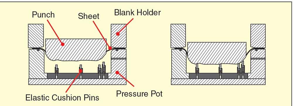
Figure 4 illustrates a tool design in which elastic cushion pins are mounted in the pressure pot. Toward the end of the SHF-P process, the sharp corners are formed mechanically by these pins rather than by the pot pressure. Thus, sharp corners can be formed mechanically and do not require large pot pressures.
About the Publication

subscribe now

The Fabricator is North America's leading magazine for the metal forming and fabricating industry. The magazine delivers the news, technical articles, and case histories that enable fabricators to do their jobs more efficiently. The Fabricator has served the industry since 1970.
start your free subscription- Stay connected from anywhere

Easily access valuable industry resources now with full access to the digital edition of The Fabricator.

Easily access valuable industry resources now with full access to the digital edition of The Welder.

Easily access valuable industry resources now with full access to the digital edition of The Tube and Pipe Journal.

Easily access valuable industry resources now with full access to the digital edition of The Fabricator en Español.
- Podcasting

In this episode of The Fabricator Podcast, Caleb Chamberlain, co-founder and CEO of OSH Cut, discusses his company’s...
- Trending Articles
1
Tips for creating sheet metal tubes with perforations

2
Supporting the metal fabricating industry through FMA

3
JM Steel triples capacity for solar energy projects at Pennsylvania facility

4
Are two heads better than one in fiber laser cutting?

5
Fabricating favorite childhood memories
