


Graduate Research Associate
Editor’s Note: This is Part II of a two-part series that discusses blank optimization and some of the process variables that affect the fracture and restraining forces in deep drawing. Part I, which appeared in the May/June 2019 issue, discussed the use of draw beads and spacers in deep drawing.
Finite element (FE) simulations can be used to predict the occurrence of fracture or wrinkles in a given deep drawing, thus reducing the number of experimental tryouts in die design and manufacturing.
Blank optimization reduces the possibility of fracture and wrinkles in the final formed part. FE analysis software can give an optimal initial blank geometry based on the final part shape and stretching desired in the material.
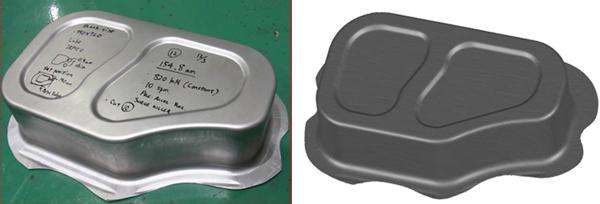
The importance of choosing the appropriate initial blank geometry is illustrated by an example die set, built by Honda, containing draw beads and spacers (see Figure 1). The process was simulated in AutoForm software for 1.2-millimeter-thick aluminum 5182-O and 1.5-mm-thick spacers; the spacer height was assumed to be uniform around the part in FE simulations, neglecting the potential elastic deflections on the tools and the press. A coefficient of friction (COF) of 0.07, obtained by reverse engineering between experiments and simulations, was used. Later, the effect of the spacer height and the COF on the part quality (part formed without fracture and minimal wrinkles) was investigated. Twenty percent thinning is assumed as the fracture criterion for aluminum 5182-O, based on recommendations by the industry.
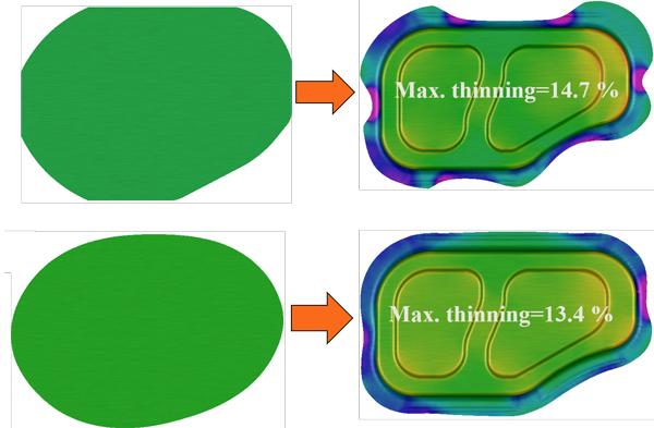
Researchers observed no fracture in the sheet metal during formation of draw bead in FE simulations and in experiments. A reduction of maximum thinning and, thus, a lower possibility of fracture was achieved by blank optimization (see Figure 2). Additionally, the flange shape obtained for the optimized blank was uniform in the simulation.
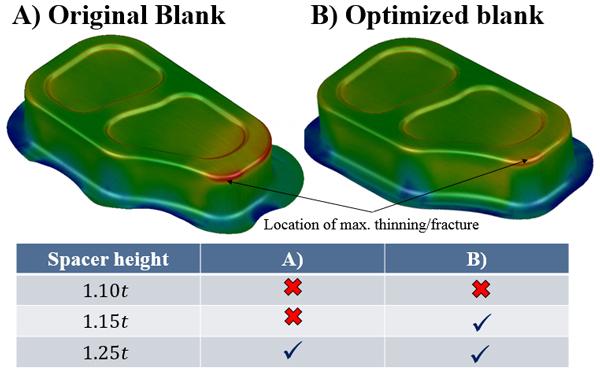
Three different spacer heights (1.1t, 1.15t, and 1.25t, where t is the sheet thickness) were chosen based on the range of spacer heights generally used in the industry. The COF was kept constant at a value of 0.07. The results indicated that the optimized blank may form successfully without fracture for a larger range of spacer heights as compared to the original blank (see Figure 3). A spacer height of 1.10t was not considered for further analysis, as it caused the sheet metal to fracture, both in original and optimized blanks.
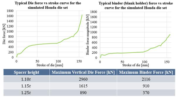
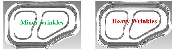
The spacer height significantly affected the die and binder forces for the optimized blank (see Figure 4). A spacer height of 1.25t caused heavy wrinkling as compared to a spacer height of 1.15t (see Figure 5). Hence, the available press and cushion capacities should be considered when choosing the best spacer height in conjunction with forming the part without fracture and wrinkles. In this study, for subsequent FE simulations, a spacer height of 1.15t was chosen.
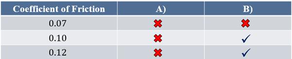
Three different COFs (0.07, 0.1, and 0.12) were considered, and the spacer height was kept constant at a value of 1.15t = 1.38 mm (see Figure 6). Since spacers were used, the COF values did not seem to affect the wrinkling and the die and binder forces for this specific case.
FE simulation is a useful resource when designing tools. Blank optimization can be done not only to improve formability of the material, but also to decrease the amount of material required to form the part. Moreover, after an analysis of the effect of COF for a given process, an appropriate lubricant can be chosen.
Increasing spacer height will increase the material flow and decrease the tool forces, but will also increase the wrinkles on the flange. Therefore, choosing the best spacer height is a compromise between wrinkling and tool forces.
Draw beads play a very important role in deep drawing of large parts; however, draw bead optimization is still under investigation at CPF. Researchers are conducting FE simulations to estimate the effect of draw bead parameters on material flow.

Professor Emeritus and Director - Center for Precision Forming


The Fabricator is North America's leading magazine for the metal forming and fabricating industry. The magazine delivers the news, technical articles, and case histories that enable fabricators to do their jobs more efficiently. The Fabricator has served the industry since 1970.
start your free subscription
Easily access valuable industry resources now with full access to the digital edition of The Fabricator.

Easily access valuable industry resources now with full access to the digital edition of The Welder.

Easily access valuable industry resources now with full access to the digital edition of The Tube and Pipe Journal.

Easily access valuable industry resources now with full access to the digital edition of The Fabricator en Español.
In this episode of The Fabricator Podcast, Caleb Chamberlain, co-founder and CEO of OSH Cut, discusses his company’s...


