


President
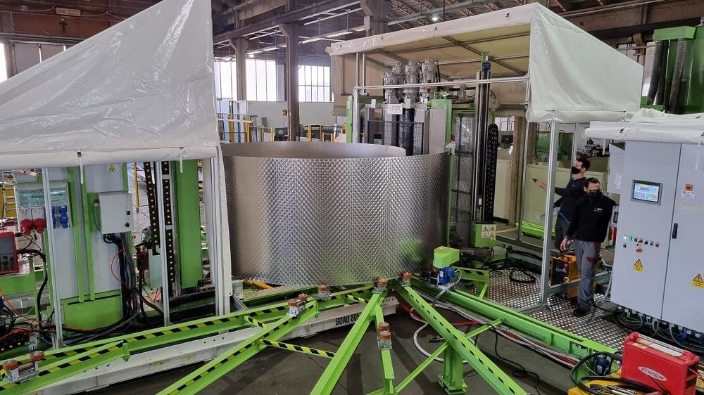
FIGURE 1. During the rolling cycle in a vertical, coil-fed system, the leading edge “curls” in front of the bending rolls. The newly cut trailing edge is then pushed toward the leading edge, tacked, and welded to create the rolled shell.
Everyone in metal fabrication is probably familiar with the rolling machine, be it of the initial-pinch, three-roll double-pinch, three-roll translating geometry, or four-roll variety. Each has its limitations and advantages, but they also share a common trait: They roll sheet and plate in the horizontal position.
A less familiar approach involves rolling in a vertical orientation. Like other methods, rolling vertically comes with its own set of limitations and advantages. The advantages almost always address at least one of two challenges. One is the effects of gravity on the workpiece during rolling, and the other involves inefficient material handling. Improving both improves workflow and, ultimately, a fabricator’s competitiveness.
Vertical rolling technology isn’t new. Its roots go back to a handful of custom systems built in the 1970s. By the 1990s, certain machine manufacturers were offering vertical rolling machines as regular product lines. The technology has been embraced by various industries, especially in the tank production arena.
Common tank and vessels often produced vertically include those used in the food and beverage, dairy, wine, beer, and pharmaceutical industries; API tanks for oil storage; and welded tanks for agricultural or water storage. Vertical rolling drastically reduces material handling; typically yields a higher-quality bend; and more effectively feeds the next stage of production for fit-up, alignment, and welding.
Another advantage comes into play in situations where material storage capacity is limited. Vertical storage of plate or sheet requires much less square footage than plate or sheet stored in the flat.
Consider a shop that rolls a shell (or “course”) of a large-diameter tank on a horizontal roll. After rolling, operators tack-weld, lower the side frame, then slip off the rolled shell. Because the thin shell bows under its own weight, the shell either needs to be supported with stiffeners or stabilizers or rotated to the vertical position.
Such an exorbitant amount of handling—feeding plate from a horizontal position into a horizontal roll only to remove and tip it for stacking after rolling—can create all sorts of production headaches. By rolling vertically, a shop eliminates all the in-between handling processes. The sheet or plate is fed and rolled vertically, tacked, then lifted in the vertical orientation to the next operation. Rolled vertically, the tank shell isn’t fighting gravity, so it doesn’t sag under its own weight.
Some vertical rolling occurs on four-roll machines, especially for smaller-diameter tanks (usually with a diameter of less than 8 ft.) that will be sent downstream and worked on in the vertical orientation. The four-roll system allows for rerolling to eliminate the unbent flat section (where the roll grasps the plate), which can be more pronounced on small-diameter shells.
Most vertical rolling for tanks occurs with three-roll, double-pinch-geometry machines, fed with sheet metal blanks or directly from a coil (a method that’s becoming increasingly common). In these setups, operators use radius gauges or templates to measure the shell’s radius. They adjust the bending roll as it contacts the coil’s leading edge, then adjust again as the coil continues to feed material. As the coil continues to feed toward its tightly wound interior, the material springback increases, and operators move the rolls to induce more bending to compensate.
The springback varies with the material properties and type of coil. The coil’s inside diameter (ID) matters. All other things being equal, a coil with a 20-in. ID is wound tighter, and exhibits greater springback, than the same coil wound to a 26-in. ID.
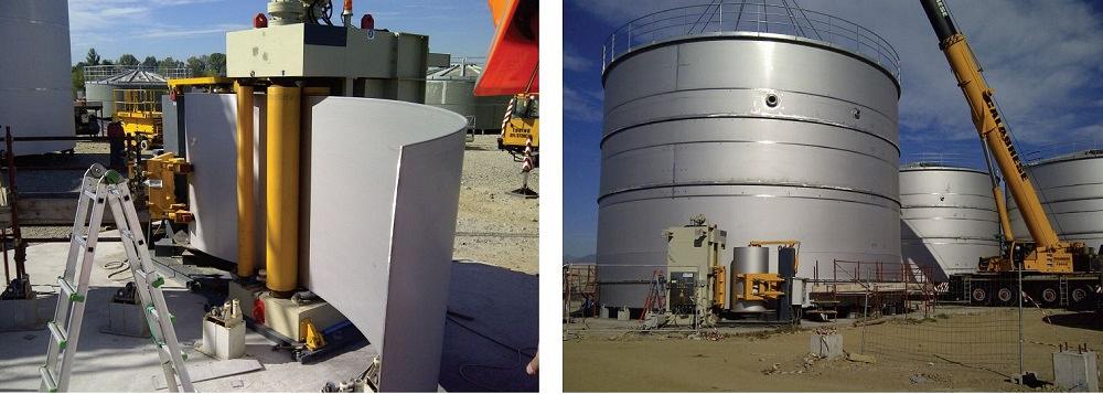
FIGURE 2. Vertical rolling has become an integral part of many storage tank field installations. Making use of a crane, the process typically starts with the top courses and progresses toward the bottom courses. Notice the single vertical weld seam on the top courses.
Note, however, that vertical tank rolling is very different from rolling heavy plate on a horizontal roll. For the latter, the operator works to ensure the plate edges mate precisely at the end of the rolling cycle. Heavy plate rolled to a tight diameter isn’t reworked easily.
When forming a tank shell with a coil-fed vertical roll, the operator can’t have the edges meet at the end of the rolling cycle because, of course, the sheet comes directly from the coil. During rolling, the sheet has a leading edge, but it won’t have a trailing edge until it’s cut from the coil. In the case of these systems, the coil is rolled to a complete circle in front of the actual bending rolls and then cut after completion (see Figure 1). After this, the newly cut trailing edge is pushed toward the leading edge, tacked, then welded to create the rolled shell.
Prebending and rerolling in most coil-fed setups aren’t efficient, which means they have drop sections (analogous to unbent flat sections in non-coil-fed rolling) from the leading and trailing edge that are usually scrapped. That said, many operations consider the scrap a small price to pay for all the material handling efficiency that the vertical roll gives them.
Even so, some operations want to get the most out of the material they have, so they opt to integrate a roller-leveler system. These resemble the four-high roller levelers found on coil processing lines, just flipped on their side. Common configurations include seven- and 12-roll levelers that use some combination of idle, straightening, and bending rolls. The levelers not only minimize the scrapped drop sections for each shell, but also increase the system’s flexibility; that is, the system can produce not just rolled components, but also leveled, flat blanks.
The leveling technology can’t replicate the results of expansive leveling systems service centers use, but it can produce material flat enough to be cut with a laser or plasma. This means that the fabricator can use the coiled material both for vertical rolling and flat cutting operations.
Imagine an operator rolling a shell for a tank section gets an order for a batch of blanks destined for the plasma cutting table. After he rolls the shell and sends it downstream, he configures the system so that the leveler does not feed directly into the vertical rolls. Instead, the leveler feeds flat material that can be cut to the desired length, creating a flat blank for plasma cutting.
After cutting a batch of blanks, the operator reconfigures the system to resume rolling tank shells. And because he’s rolling leveled material, material variability (including differing levels of springback) is less of an issue.
In most sectors of industrial and structural fabrication, fabricators aim to increase the amount of shop fabrication to simplify and streamline on-site fabrication and installation. For the fabrication of large tanks and similarly massive structures, however, this rule doesn’t apply, mainly because of the incredible material handling challenges such work creates.
Operated on the job site, coil-fed vertical rolls simplify material handling and streamline the entire tank fabrication process (see Figure 2). It is far easier to transport a metal coil to a job site than a series of huge sections rolled in the shop. Also, rolling on-site means that even the largest-diameter tanks can be fabricated with just one vertically welded seam.
Bringing levelers on-site can make the on-site operation even more flexible. This is a common option for field tank production where the added capability allows a fabricator to utilize straightened coil material to construct tank decks or bottoms on-site, eliminating transportation between the shop and job location.
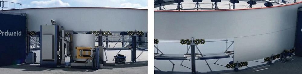
FIGURE 3. Some vertical rolls are integrated with on-site tank production systems. The jacks lift previously rolled courses upward, eliminating the need for a crane.
Some field operations have vertical rolls integrated within a larger system—including cutting and welding units used in conjunction with unique lifting jacks—that eliminates the need for an on-site crane (see Figure 3).
The entire tank is built from the top down, yet the process starts from ground level. Here’s how it works: The coil or plate material travels through a vertical roll, positioned mere inches from where the tank wall will stand in the field. The wall then is fed into guides that carry the sheet as it feeds around the entire tank circumference. The vertical roll stops, the ends are cut, and a single vertical seam is tacked and welded. Stiffening rib components then are welded to the shell. Next, the jacks lift the rolled shell upward. The process repeats for the next shell underneath.
The circumferential weld is made between the two rolled sections, after which the tank roofing components are fabricated into place—all while the structure is still close to the ground, with only the two uppermost shells fabricated. Once the roof is complete, the jacks lift the entire structure up for the next shell, and the process continues—all with no crane required.
When the operation reaches the lowest courses, thicker plate comes into play. Some field tank producers use 3/8- to 1-in.-thick plate, even heavier in some cases. Plates don’t come in coil form, of course, and can be only so long, so these lower sections will have multiple vertical weld seams that connect the rolled plate sections. Regardless, with a vertical machine on-site in the field, plate material can be unloaded one time and rolled on-site for utilization directly in the tank construction.
Such tank building systems epitomize the material handling efficiency made possible (at least in part) by vertical rolling. Of course, like any technology, vertical rolling isn’t ideal for every application. Its suitability depends on what handling efficiencies it creates.
Consider a fabricator that installs a non-coil-fed vertical roll for a mix of jobs, the majority of which are tight-diameter shells that require prebending (bending the workpiece leading and trailing edges to minimize the unbent flat). Those jobs are theoretically feasible on a vertical roll, but prebending is a lot more cumbersome in the vertical orientation. In most cases, vertical rolling a large number of jobs that require prebending just isn’t efficient.
Besides material handling issues, fabricators integrate vertical rolling to avoid fighting gravity (again, to avoid the bowing of large, unsupported shells). But if an operation involves only rolling plate strong enough to keep its shape throughout rolling, rolling that plate vertically makes less sense.
Similarly, asymmetrical jobs (ellipses and other unusual shapes) are often best formed on horizontal rolls with, if needed, overhead supports. In these cases, the supports do more than just prevent gravity-induced sagging; they guide the work through the rolling cycle and help maintain the workpiece’s asymmetrical shape. The challenges of manipulating such work in a vertical orientation would likely wipe out any benefit of vertical rolling.
The same thinking applies to cone rolling. Rolling a cone relies on friction between the rolls and differing amounts of pressure from one end of the roll to the other. Roll a cone vertically, and gravity adds yet more complications. Unique cases might exist, but for all intents and purposes, cone rolling vertically just isn’t practical.
Using three-roll translating geometry machines vertically also usually isn’t practical. In these machines, the two bottom rolls move side to side in either direction; the top roll can adjust up and down. The adjustments allow these machines to bend complex geometries and roll a range of material thicknesses. In most cases, those benefits wouldn’t be enhanced by rolling in the vertical orientation.
When choosing a plate roll, it is important to carefully and thoroughly research and consider the machine’s intended production use. Vertical plate rolls are more limited in function than traditional horizontal rolls but offer critical advantages in the proper application.
Compared with their horizontal cousins, vertical plate rolls typically have more basic design, operation, and construction characteristics. Moreover, the rolls often are oversized for the application, which eliminates the need to incorporate crowning (and the barreling or hourglass effects in the workpiece that happen when crowning isn’t tuned correctly for the job at hand). When coupled with a decoiler, they form thin material for the entirety of a shop tank that typically doesn’t exceed 21 ft. 6 in. in diameter. Much larger-diameter top courses of field-erected tanks might have only one vertical weld seam, as opposed to three or more with plate production.
Again, the biggest advantage with rolling vertically comes where a tank or vessel needs to be constructed in a vertical orientation because of the effect of gravity on thinner material (say, up to 1/4 or 5/16 in.). Producing horizontally would force the use of stiffening or stabilizing rings to hold the round of the rolled part.
The vertical roll’s true advantage is in material handling efficiency. The fewer times a shell needs to be manipulated, the less chance there is for damage and rework. Consider the stainless steel tanks now in high demand from the busier-than-ever pharmaceutical industry. Rough handling might cause cosmetic issues or, even worse, break the passivation layer and create a contaminated product. A vertical roll, working in concert with cutting, welding, and finishing systems, can reduce the handling and the chance for contamination. When this happens, a fabricator can reap the benefits.

The Fabricator is North America's leading magazine for the metal forming and fabricating industry. The magazine delivers the news, technical articles, and case histories that enable fabricators to do their jobs more efficiently. The Fabricator has served the industry since 1970.
start your free subscription
Easily access valuable industry resources now with full access to the digital edition of The Fabricator.

Easily access valuable industry resources now with full access to the digital edition of The Welder.

Easily access valuable industry resources now with full access to the digital edition of The Tube and Pipe Journal.

Easily access valuable industry resources now with full access to the digital edition of The Fabricator en Español.
In this episode of The Fabricator Podcast, Caleb Chamberlain, co-founder and CEO of OSH Cut, discusses his company’s...


