


Contributing Writer
Figure 1a
This is the end goal—a prototype of a reservoir. The intended use of that prototype guides the CAD techniques applied.
Editor's Note: If you would like to download the 3-D CAD files associated with this column, click here.
As a CAD project, the reservoir shown in Figure 1a includes cross-breaks in sheet metal, welded fittings and seams, mechanical assembly, and the use of third-party components. As a realistic prototype—albeit virtual—the fluid fills the interior volume of the container. This makes for accurate prediction of the reservoir’s capacity.
For extra fun, the top of the fluid level in the tank can be animated in a motion study. The depth of the sensing probe may be adjusted as part of evaluating the design. The exploded view in Figure 1b will be useful in various forms of product documentation.
The design intent for this model is primarily to produce fabrication drawings for the sheet metal and welded parts. Secondary goals include an accurate virtual prototype as well as a detailed bill of materials to help with purchasing.
The intent of the fluid model is accurate prediction and visualization of volume. The CAD details of fluid volume shown in Figure 1b are revealed in Figure 2a. In Figure 2a, the fluid model is just an oversize blob. In Figure 2b the Cavity Tool subtracts the tank model from the fluid model. In Figure 2b, the extra blob fluid has been removed via the Cavity Tool.
Because the sheet metal model for the tank is not seamless, the Cavity Tool left little runners that connect the good interior volume to the unwanted blob volume of fluid. A small cut was required to trim fluid that is leaking in the tank’s four corners. This creates a multibody part. After that cut was complete, the extra body was deleted.
The intent of the model of the lid is fabrication. Fabrication will involve several trade skills, such as purchasing off-the-shelf parts, sheet metal fabrication, welding, quality control, and assembly. The lid is modeled as two assemblies, a nested matryoshka doll in CAD.
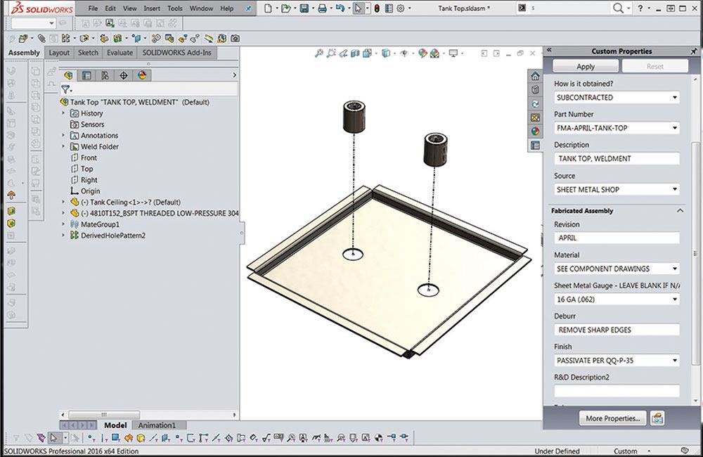
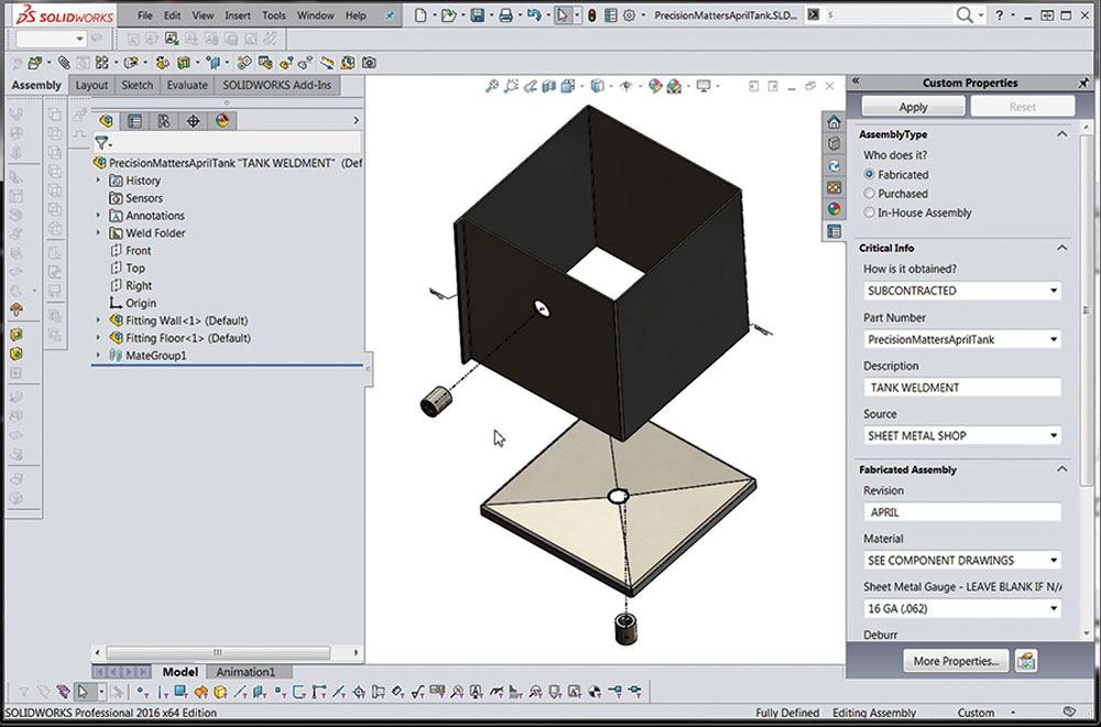
The inner assembly is a weldment, shown in Figure 3a, of sheet metal and off-the-shelf couplings.
The model for the coupling was obtained as a download. The model for the sheet metal lid is custom-sized to achieve the reservoir size needed. As a sheet metal part, it takes advantage of CAD tools for prediction of the flat layout.
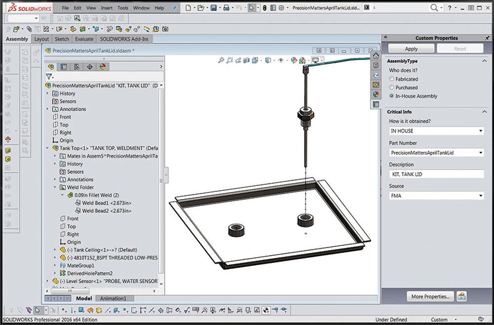
The outer level of nesting for the tank lid is shown in Figure 3b. It’s a kit made up of the welded sheet metal lid and a sensing probe (see Figure 3c) that is screwed in place. The tank lid assembly model creates a bill of materials for purchasing as well as illustrations for training assemblers.
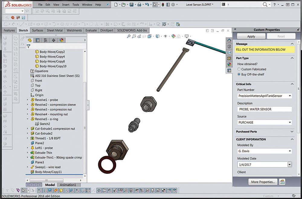
Figure 1b
The design intent includes production of exploded views, fabrication drawings, welding instructions, and simulation of probe depth and fluid level.
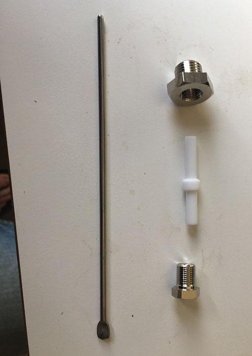
The intent is to purchase this probe as an off-the-shelf kit. However, the supplier does not do CAD. We know the probe is 6 in. long and that the mounting thread is ¼ BSPT.
The goals for this model are thread mounting, assembly training, and to simulate the range of position for the probe.
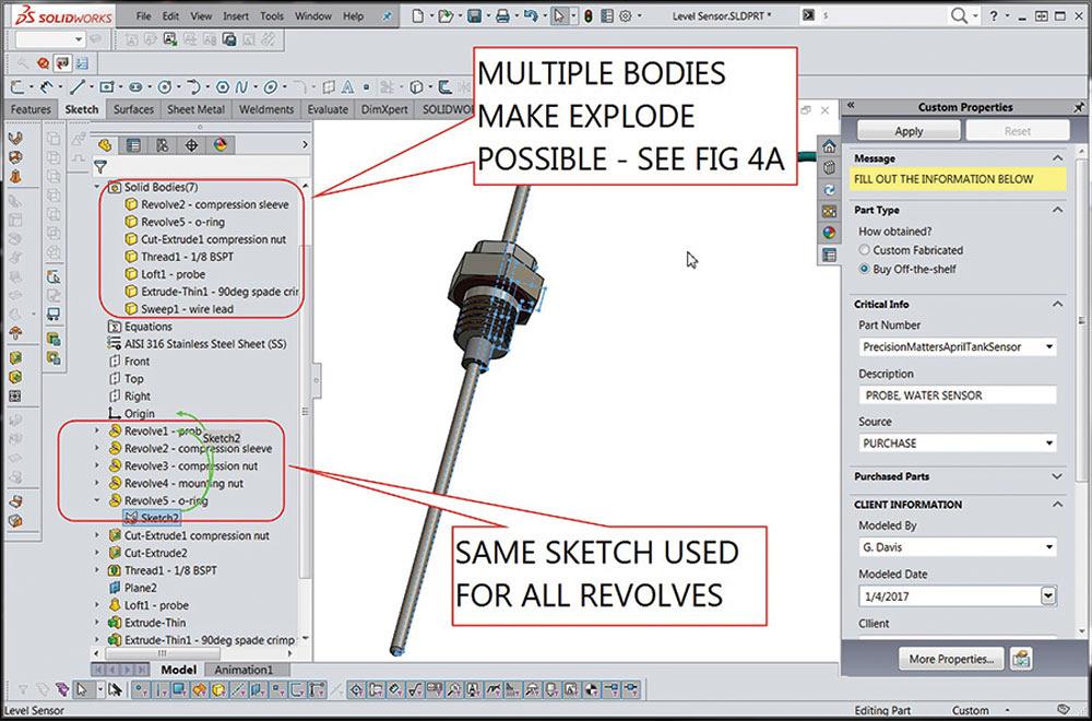
The probe kit model shown in Figure 4a is an example where low CAD labor is the principal design intent. The plan is to avoid assembly mate features as a means to save time.
A couple of CAD tips are revealed in Figure 4b:
1. Don’t model detail you don’t need. Since this model is not going to be used for fabrication, the thread pitch of the internal compression nut does not matter and can be omitted.
2. Multibody modeling with all parts modeled as bodies in one file cuts down on file name clutter.
A single sketch, Sketch2, was used when creating the bodies for the probe, insulator, O-ring, and nuts. Sketch2 was consumed by the first revolved feature—the probe’s body.
Here’s another CAD tip: Even though a sketch is consumed by an extruded feature, it can be used again as the sketch for another feature. “Consumed” just means it collapsed in the tree of history shown in the Feature Manager. Click to expand, and there it is.
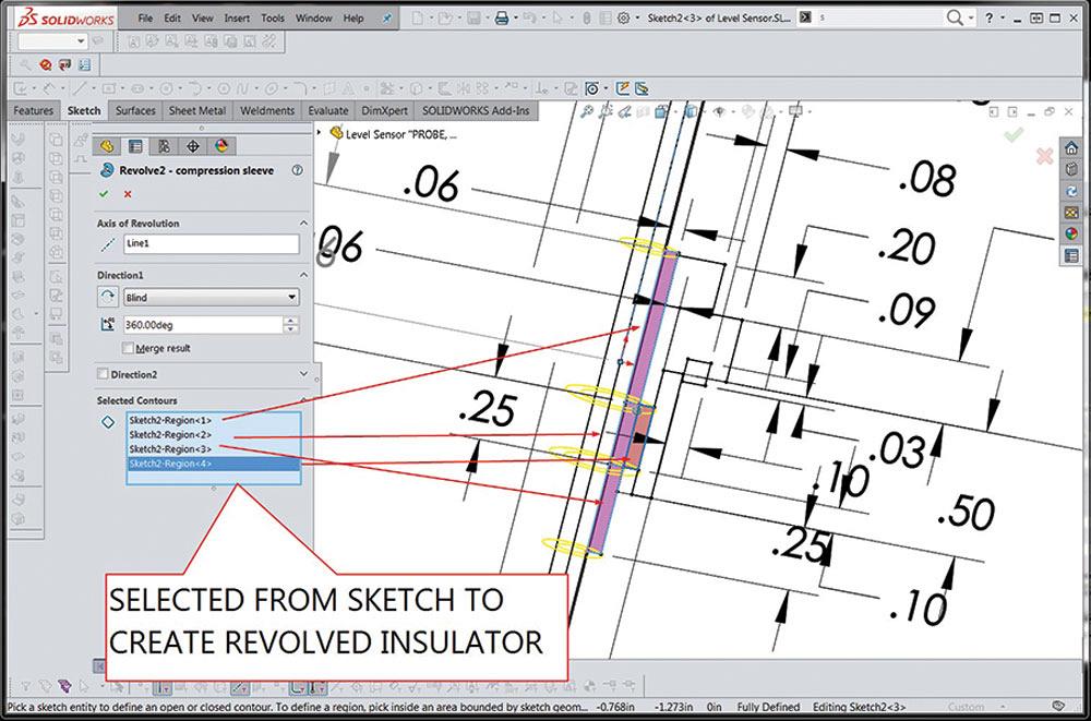
Figure 4c reveals that Sketch2 has outlines for all of the parts with many overlapping sketch segments, which are not pretty to look at, but very quick to sketch. The author got carried away adding dimensions while scaling the model to resemble the photo.
Here’s one more CAD tip: To create a body, the Contour Select tool selects regions of the sketch. Figure 4c demonstrates the setup for the model of the insulating sleeve.
Figure 2a
Interior fluid volume starts with an oversize blob.
An exploded view of the tank weldment is shown in Figure 5a. A design goal for the tank assembly is fabrication. To that end, flat layouts will be helpful. Drawings to specify the location of welds will be needed as well. Instead of multibody, this kit of parts will be modeled as an assembly of separate models.
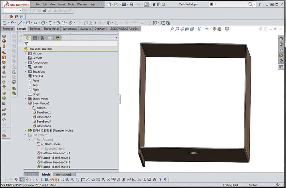
The sheet metal model for the ideal tank wall is shown in Figure 5b. The goal is to replace seam welds with bent sheet metal—thus a single seam in the corner.
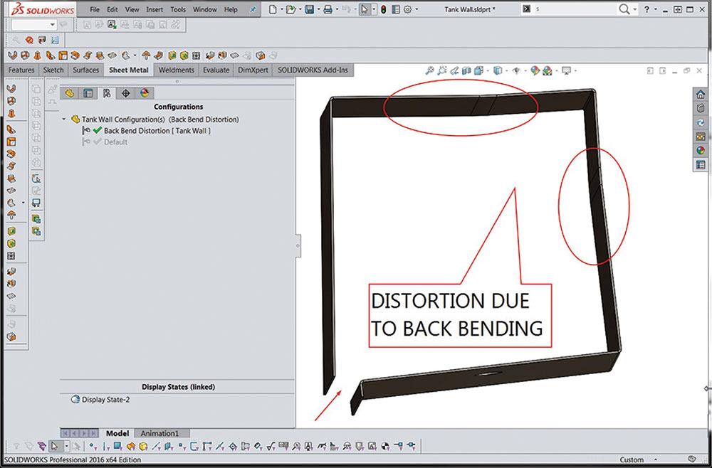
A bridge-tool would be needed to form this part in a standard press brake. Otherwise, the part will crash into the frame of the brake during the last bend (see Figure 5c). This distortion might be acceptable, since the part will flatten some during welding.
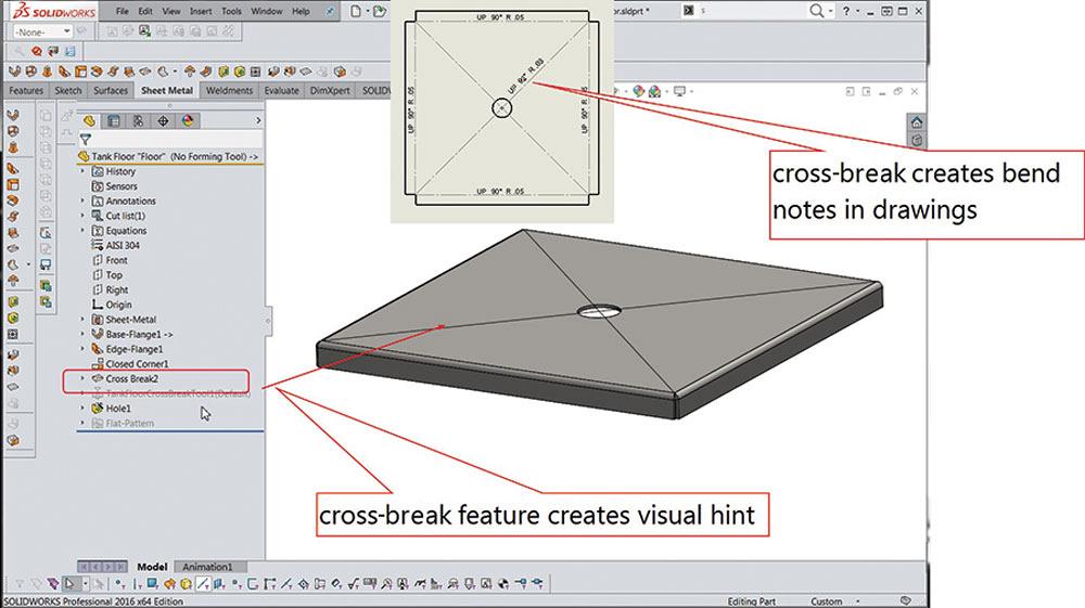
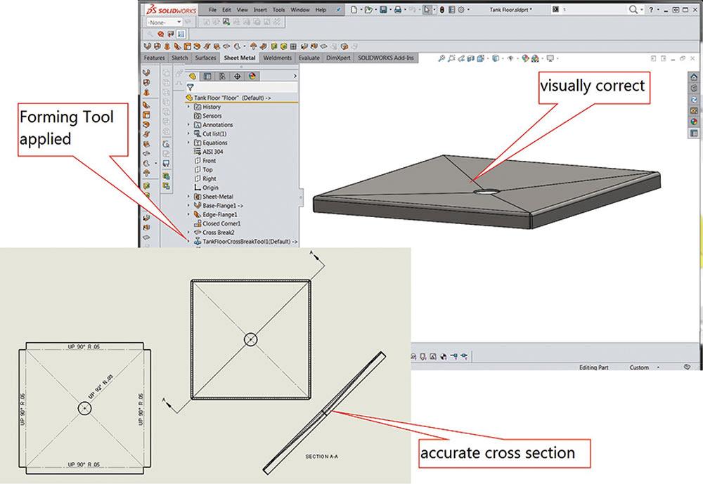
The tank floor features a cross-break to help with draining. For speedy modeling, the Cross Break tool is handy (see Figure 6a). This tool does not create bent geometry; it merely creates notes on the flat layout. An example of the note is shown as in inset in Figure 6a.
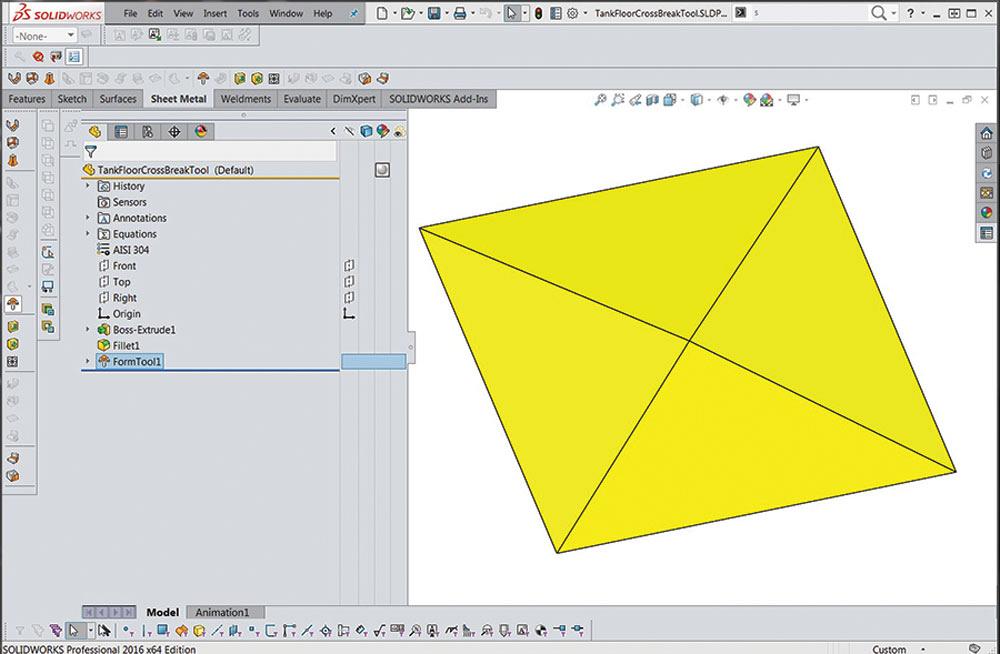
A CAD tool call the Form Tool comes into play to achieve a visually faithful cross-break. Figure 6b shows the Form Tool model, which is a separate model from the sheet metal floor. Forming tools have their rules, such as being stored in a specially designated folder among other details, and represent what a hard tool would do to sheet metal in the real world.
In Figure 6c the result of applying the Form Tool to the sheet metal part is shown: an accurate cross-break in both 3-D and in 2-D.
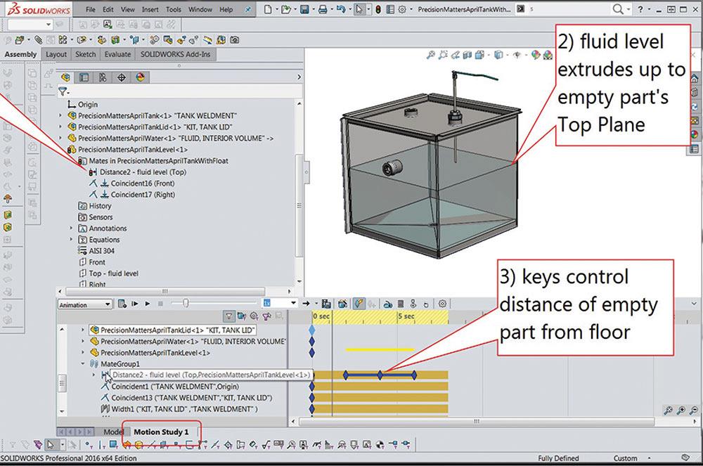
With the component models of the reservoir complete, a Motion Study can be used to animate the fluid level in the tank. The setup is shown in Figure 7. The basic idea is to extrude the model for the fluid up to a surface that can be positioned by Motion Study keys.
In this animation example, a part is created that represents the top of the fluid volume. The part does not need to have any features other than the default planes—an empty part. The part is mated in the reservoir at a distance from the floor. That Distance Mate will be used by Motion Study, as shown in Figure 7.
We offer downloads of both the AVI and the 3-D models used to create the illustrations in this article at www.thefabricator.com/page/shop-technology-and-3-d-cad-downloads.
Gerald Davis uses CAD software to design and develop products for his clients at www.glddesigns.com. From 1984 to 2004 he owned and operated a job shop. Gerald would love for you to send him your comments and questions. You are not alone, and the problems you face often are shared by others. Send your questions and comments to dand@thefabricator.com.


The Fabricator is North America's leading magazine for the metal forming and fabricating industry. The magazine delivers the news, technical articles, and case histories that enable fabricators to do their jobs more efficiently. The Fabricator has served the industry since 1970.
start your free subscription
Easily access valuable industry resources now with full access to the digital edition of The Fabricator.

Easily access valuable industry resources now with full access to the digital edition of The Welder.

Easily access valuable industry resources now with full access to the digital edition of The Tube and Pipe Journal.

Easily access valuable industry resources now with full access to the digital edition of The Fabricator en Español.
Seth Feldman of Iowa-based Wertzbaugher Services joins The Fabricator Podcast to offer his take as a Gen Zer...


