


President
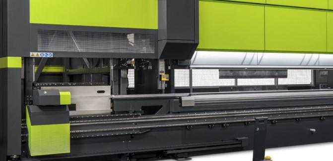
Belt- and pulley-driven electric press brakes exert force evenly across the entire bed. Their precision and speed introduce a host of opportunities.
The hydraulic press brake forever changed sheet metal manufacturing. Its programmable upper beam, or ram, could descend to just the right depth of penetration to air-form a workpiece to the desired bend angle. The machine helped make the precision sheet metal industry what it is today.
Like any technology, though, hydraulic press brakes have their drawbacks. Hydraulics need to be maintained, and their “always on” nature can consume a lot of energy. Another complication comes with the way hydraulic press brakes apply force, with two hydraulic actuators applying pressure on either side of the bending bed. During the bending cycle, the hydraulic brake’s bending force focuses near those hydraulic cylinders on either side of the bed, then diminishes near the middle. That uneven distribution spurs the need for crowning. Insufficient crowning can lead to the familiar “canoeing” along the bend line, where the internal bend angle is less near the ends and greater in the center.
Back in the 1990s, engineers asked a poignant question: What if we could minimize or even eliminate the need for crowning? That began the development of a new kind of press brake, an electric one that applied force in a novel way— though their concept was rooted in a very old technology: the mechanical advantage of the pulley.
The mechanical advantage of pulley systems has shaped industry for centuries, but it’s usually associated with lifting force. The belt- and pulley-driven electric press brake flips the concept and uses an extensive pulley system to exert force downward. Instead of pulleys lifting an object, a fixed bottom row of pulleys “pull” an upper row of pulleys downward against the force coming from two compression springs on either side of the ram (see Figure 1).
The steel-reinforced belts, coated with a hard polyurethane, serpentine through multiple pulleys. This arrangement gives mechanical advantage for two servomotors, one on the top left and another on the top right of the upper beam. The greater number of pulleys, the greater the mechanical advantage and the more tonnage can be achieved.
Position sensors on each side of the ram ensure parallelism between the upper and lower beams. Once the stroke reaches bottom-dead-center, forming tonnage is released and the springs take over to effectuate the return stroke. The return stroke is programmable; that is, it can return to a defined open height.
When the ram is at bottom-dead-center, the springs are in their most compressed state. In an idle, “do nothing” state, the machine’s springs in combination with the electric brakes in the motors hold the ram at the open height. This adds another layer of safety to the overall design. If something should happen to the belt drives or servomotor, the ram won’t drop, damage tooling or (worse yet) injure the operator or others nearby. Instead, the springs will push the ram up and return the machine to its idle state.
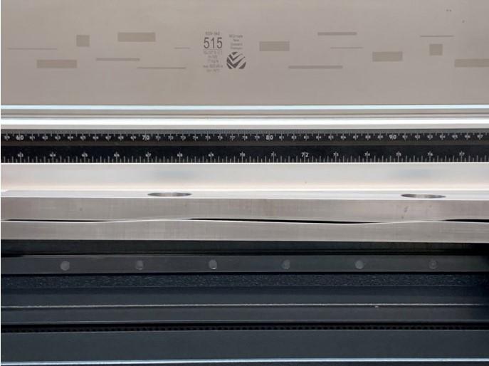
Evenly distributing the forming force across the upper beam greatly limits the amount the upper beam deflects during bending (less than 2%). But what about the lower beam? To counteract deflection there, some electric brakes have two cutouts, or “slices,” on either end of the beam plate (see Figure 2).
The slices tackle the deflection problem in a unique way. Deflection in the lower beam is greatest in the center, less on the ends. Instead of using a crowning system that “pushes up” on the highly deflected center of the lower beam, the slices actually increase how much the lower beam deflects on both ends. This brings the deflection amount on the ends closer to the amount of deflection in the middle of the lower beam. During forming, this arrangement creates a straight, level surface from one end of the lower beam to the other.
In some cases, electric brakes do have crowning systems in the lower beam to compensate for ever-so-slight deflection (see Figure 3). This might be for critical applications involving bending over the full length of the bed, those involving small V die openings (relative to the sheet thickness), high bending forces, or high-tensile-strength material.
Because the crowning table is mitigating only minimal amounts of deflection, it needn’t move much to compensate. For instance, on a 110-ton, 10-ft. electric press brake, equipped with the slices in the lower beam, bending a workpiece over the entire length of the bed at full tonnage might create only 0.3 mm of deflection. Most conventional applications, including sheet metal parts with bend lengths less than a third of the overall bed length, don’t require crowning.
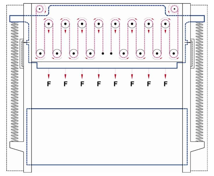
FIGURE 1 Belt- and pulley-driven electric brakes distribute force evenly across the bed, producing minimal deflection in the upper beam and minimizing the need for crowning. The downward force pushes against two compression springs, which lift the upper beam after reaching bottom-dead-center.
Early versions of belt- and pulley-driven electric press brakes were small, low-tonnage machines with 4- or 5-ft. beds. The technology maxed out at about 35 tons of forming force. This was the mid-1990s, when servomotors had their limitations, reinforced belt designs hadn’t been perfected, and the overall concept was novel.
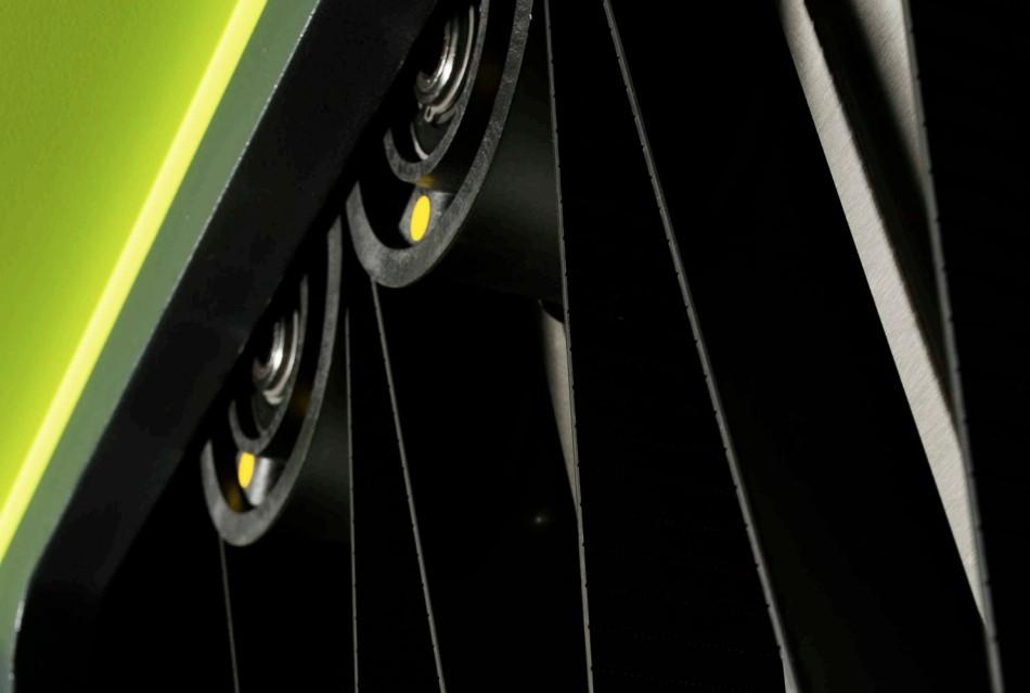
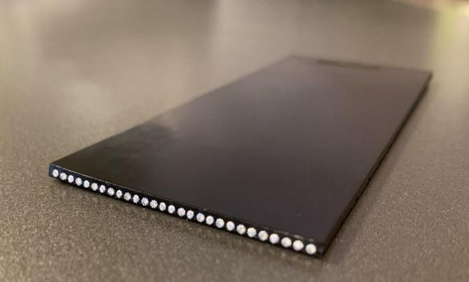
Not long after their introduction, though, 50-ton machines began entering the market. Servomotor technology improved, as did the design of the belt, due to developments in the elevator industry (see Figure 4). The pulley rolls themselves, initially made of steel, were now a lightweight composite, fiber-reinforced material. Their reduced weight helped shorten the ram’s stopping time.
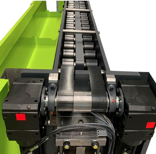
Designers also increased the number of pulleys placed across the upper beam. The more pulleys a machine had, the higher forming forces it could achieve—all while distributing forming force and nearly eliminating deflection in the upper beam. Machine beds became longer and tonnages grew (see Figure 5).
Although eliminating deflection was the impetus behind the machine’s development, other benefits soon came to light, the most obvious being energy consumption. The electric brake has no continuously running motor; it uses energy only when it’s going downward.
Electric machines also have relatively simple maintenance regimens. Techs need to keep the servomotors dust free. Furthermore, they need to clean and grease the ballscrews and linear guides on the backgauge. Depending on the environment, they also need to clean the spring packs occasionally. But the machine drive itself has no hydraulics to maintain and uses no oil that could leak.
Each pulley represents about 3 tons of force, and the number of pulleys determines how much energy can be multiplied from the energy source—that is, the servomotor. Considering the power achieved through mechanical advantage, why not continue the concept and design ever-more-numerous pulleys? It’s theoretically possible, but there’s a tradeoff in speed. A dense collection of dozens of pulleys could greatly increase the forming power from a small servomotor, but the ram would move very, very slowly.
Today’s belt- and pulley-driven electric brakes come in models up to 300 tons. These machines have a so-called dual drive belt system with eight servomotors, four at each side of the machine. This arrangement gives the optimal mix of speed, control, and available forming tonnage.
Could larger servomotors increase speed? Yes, but there’s a balance here as well. At a certain point, a faster ram-approach speed gives diminishing returns. This has to do with the number of starts and stops a press brake performs during a bending cycle. Smaller motors give a shorter stopping time to the ram, an important feature for safety reasons.
A large portion of the speed gains from an electric brake come from the machine’s quick reaction time. An operator steps on the pedal, and the ram starts moving nearly instantaneously. Speed gains also come from having programmable open heights (daylight), with the ram retracting to a point that’s best for a particular application.
Put another way, ram movement is just one part of the overall cycle time between the end of one bend and the beginning of the next. The operator needs to reposition the part as the backgauges move, then step on the foot pedal to actuate the bending cycle. Modern electric press brake design has been optimized to make the entire bend cycle as efficient as possible.
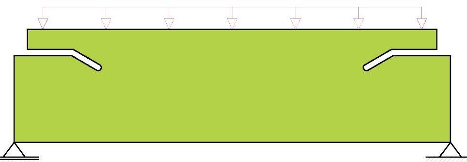
FIGURE 2 Slices in the lower beam increase deflection on the ends, matching the deflection experienced in the middle of the bed. During forming, this creates a straight line from one end of the bed to the other
Available forming tonnage rises toward the center of the bed, with maximum available tonnage at the bed centerline, similar to a hydraulic machine. Available tonnage hinges on a bend’s center of load. A workpiece’s 2-ft. bend might extend to near the end of the bed, where forming tonnage is limited, but its center of load is closer to the center of the bed. Because of this, the machine has plenty of forming tonnage available.
Bending a workpiece at the outer ends of the bed is possible because of the O-frame construction, which allows the backgauge fingers to travel along the complete working length of the machine. In most C-frame constructions, the side frames limit the working area of the backgauge fingers.
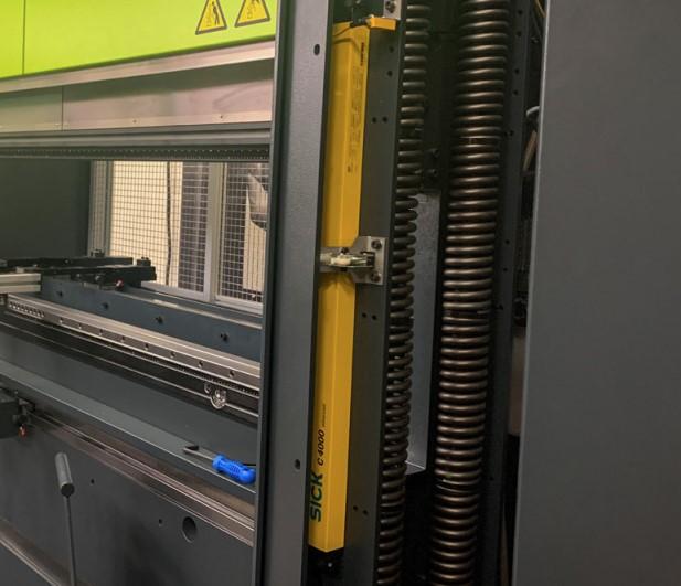
When operators start working on an electric brake, they immediately notice the open space behind the bed, and the fact that backgauges can access the very ends of the workspace. There’s no side frame in the way. Why? Because belt- and pulley-driven electric brakes take advantage of the O-frame design. No obstruction behind the tool bed gives operators more room to gauge large or odd-shaped parts. The O-frame’s pillars house the compression springs as well as the brake’s integrated safety light guards (see Figure 6).
The light guards remain active during high approach speeds, a fact that allows the ram to remain at high speed until it slows to a bending speed just above the workpiece. Put another way, the ram spends less time moving through air and more time actually bending.
The safety light guard not only can be used as a safety device. It also can be used as ram-starting device to simulate the foot pedal. When an operator leaves the working area of the machine with the workpiece, the safety system notices that the zone in front of the machine is clear, which causes an automatic start of the machine without any intervention of the operator. On the mute point (change-over point from high approach speed into low bending speed), the operator again controls the movement of the ram. This function can also be operated in such a way that the safety light guard can start and operate the complete closing stroke of the ram. No foot pedal operation is needed.
O-frame machine designs have plenty of advantages. Beyond having increased working space behind the machine, the machines are rigid, symmetrically designed, and less susceptible to distortion. Considering all this, why have C-frames been the norm in press brake machine design? The reason stems from the way operators historically have loaded tooling—from the side.
Product batches have become smaller, thus resulting in more tool changes. Before segmented, precision-ground punches and dies became the norm, operators would slide long tools from the side into the machine. Today, most operators load vertically segmented tools from the front into the machine (more and more often in combination with automatic tool clamping), a practice that opened the door to the O-frame design.
Still, O-frame machines do have certain drawbacks. They can’t be designed in a tandem configuration, for instance. Also, certain bending applications require open space to the left or right of the bed. But perhaps the most significant limitation has to do with what has become a game-changing technology in the world of high-product-mix production: the automatic tool changer (ATC). Many efficient ATC technologies feed tools from the side, and that requires a C-frame machine—a design that’s now available in some of the most recent electric press brakes (see Figure 7).
The shift required a significant redesign, mainly because of the compression springs on either side, which lent themselves to an O-frame design. To adapt the same concept to a C-frame, these new electric brakes rely on specialized gas springs. They serve the same role as the compression springs in the O-frame design, but within the space allowed in a C-frame, leaving the ends of the bed open for integration with an ATC. This also allows the belt- and pulley-driven machines with a C-frame to be integrated in a tandem setup.
Every technology has its advantages and disadvantages, and one drawback of electric brakes, at least at present, is their tonnage limits. Industry likely will always have a use for hydraulic and hybrid-drive hydraulic systems, especially when forming requires higher tonnages.
But for those focusing on precision sheet metal, precise ram movement, high positioning repeatability, and short production cycle times, the electric press brake is becoming increasingly popular. Servo-driven systems have long had a place in laser cutting and punching. Today, they’re increasingly finding a place in the bending department—a trend that’s sure to continue.

The Fabricator is North America's leading magazine for the metal forming and fabricating industry. The magazine delivers the news, technical articles, and case histories that enable fabricators to do their jobs more efficiently. The Fabricator has served the industry since 1970.
start your free subscription
Easily access valuable industry resources now with full access to the digital edition of The Fabricator.

Easily access valuable industry resources now with full access to the digital edition of The Welder.

Easily access valuable industry resources now with full access to the digital edition of The Tube and Pipe Journal.

Easily access valuable industry resources now with full access to the digital edition of The Fabricator en Español.
In this episode of The Fabricator Podcast, Caleb Chamberlain, co-founder and CEO of OSH Cut, discusses his company’s...


