


The CNC boosts sheet and plate rolling throughput
Intelligent controls automate the subtle craft of rolling
For the right application, CNC rolling allows the less experienced to produce complicated shapes.
Over the past 35 years, NCs and CNCs in metal fabrication have become increasingly sophisticated. They control different axes within robotic press brake cells, punching systems with material handling, laser systems with material handling and storage systems, robotic welding, and more.
Even so, one area seems to have fallen behind: sheet metal and plate bending rolls. However, advancements in controls and their software are starting to boost rolling throughput in significant ways.
In many cases the technology has allowed rolling to adapt to variations in material, and modern four-roll CNC machines can be seen producing complicated parts in as little as 30 seconds. Like any technological advancement, intelligent rolling controls have their limits, but in recent years especially, the CNC on rolling machines has had great success.
Historical Perspective
Before the advent of digital readouts, roll operators made a record of the position of the bending roll to repeat a job. They would measure the lower-roll positions manually, perhaps using a tape measure or rule, or using an indicator that came with a machine (see Figure 1).
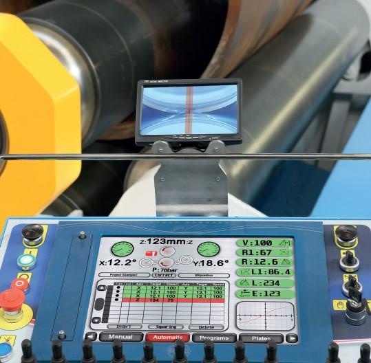
In addition to measuring roll position, digital readouts made for easy measuring of lineal travel (see Figure 2). They were useful in being able to control the flat area. Once the operator correlated roll position with workpiece travel information, he or she could create a record that served as a “program” of sorts, to be used the next time the roll ran the job. The advent of numerical control allowed the operator to store both roll positions and travel information to complete a part (see Figure 3).
Early controls had no real “intelligence.” They didn’t allow the true blending of the radius as used on parts such as square tanks, ellipses, and ovals. These required the ability to make a smooth transition between different radii and (as is the case with square tanks and similar complex work) between curved and flat portions of the part. For controls to be able to perform such smooth transitions automatically, they needed smarter algorithms.
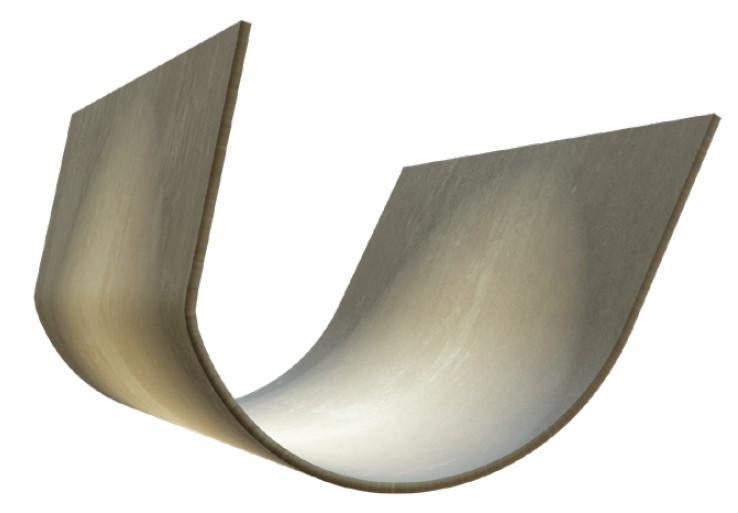
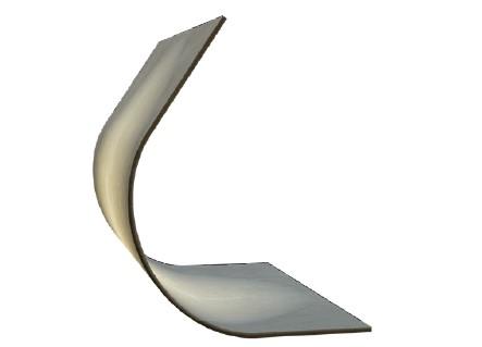
Early control systems could, without manual programming, roll cylinders and other shapes with sharp transitions, producing what could look like a press brake-formed part (see Figure 4). But they couldn’t “ease in” to create a smooth transition between different radii (see Figure 5). They couldn’t roll and adjust at the same time. Machines operated under a simple point-to-point system.
What Machines Benefit From a CNC?
Two-roll machines can be extremely productive, but they’re usually used for a specific job or jobs and with an NC. As production systems, two-roll machines with even the most basic controllers can roll part after part at high speeds, often in as little as 10 seconds. They might incorporate sophisticated controllers for associated automation such as material feeding or offloading systems. But the rolling process itself typically wouldn’t gain the full benefits and versatility out of a top-of-the-line CNC.
Most people looking for controlled bending rolls are not considering three-roll double-pinch or variable-axis machines, though NCs are available for certain applications. They don’t really lend themselves to CNC operation, because the rolls are not constantly pinching the plate for applications requiring prebending at both ends. Similarly, single-pinch machines can be used with a CNC, though they’re not ideal for most applications. But four-roll machines, be they planetary or lineal, are ideal for CNC operation.
The beneficial use of a CNC has to do with how material must be moved in the machine through the rolling cycle. To prebend both ends or use a reference point requires a constant reference point. For prebending both ends on three-roll double-pinch machines, the plate is usually clamped, released, and clamped again. When the material moves, the control can lose the material’s true position. In a four-roll machine, the middle-bottom roll pinches the material throughout the entire rolling cycle. In this way, the control “knows” the plate position throughout the process.
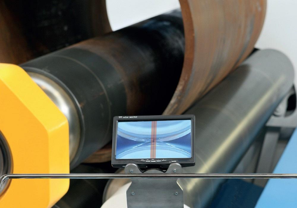
A camera shows a close-up of the radius being formed on a plate roll.
Programming the Plate Roll
Intelligent CNCs today use factory-developed algorithms tailored for the rolling process. To create programs on the CNC, operators can choose from a library of shapes, then enter the required data. This can include material length, thickness, material type, yield strength, and other items depending on the shape. On parts with a blended or changed radius or diameter, for instance, it is critical to know where the blending is to begin and end. A corrections page on the control allows operators to tweak the program if necessary. In addition, some controls allow for the import of DXF files.
A Note on Capacity
A machine’s “CNC capacity” is not its “rated capacity” or “prebending capacity.” It is something less, usually about 40% of its rated capacity.
Consider a machine with a rated capacity to roll up to 1-in.-thick, 36,000-PSI-yield-strength steel in multiple passes. This means the machine can roll this material down to a diameter between three and five times the top-roll diameter, depending on the manufacturer. This same machine rolling the same material would (again, depending on the manufacturer) likely have a prebending capacity of 0.625 in. over multiple passes, down to a minimum rolling diameter between 1.2 and 1.5 times the top-roll diameter, with the flat ends between 1.5 and 2 times the material thickness. Minimum diameters as tight as 1 times the top-roll diameter are achievable on certain material thicknesses.
This same machine would likely have a CNC capacity of about 0.40 in. This is because the control algorithms look for “one-pass rolling,” as none can accurately calculate the influence of the weight and position of the plate during subsequent passes.
Material Factors
Does the CNC on a plate roll really work? Although nothing is perfect, CNC-based systems have had great success. The best chance of success comes when the operator or programmer knows the real properties of the material they are using, such as yield strength and actual thickness. In fact, rolling any shape can be influenced by material grain, the material’s exact thickness and yield strength, the plate temperature, along with how the material was processed before it reached the roll.
Options like top and side supports can help. The top support, for instance, can help support the workpiece and size the part. Say you’re rolling 10-ga. material to a 70-in. inside diameter. Unfortunately, the material bows under its own weight after half the cylinder or more is rolled. This not only creates an inconsistent diameter, but also increases the chance that the plate ends will overlap. In other words, you would be rolling a double material thickness.
In this case, you might set the top support to a lower height (smaller diameter). Once the cylinder’s leading edge is over the top support, you’d move the top support to 70 in. With the cylinder diameter precise and consistent, its edges won’t overlap, preventing you from rolling a double material thickness.
What about material irregularities? For instance, certain materials might have their own peculiarities, even beyond variation in yield strength. To accommodate this, modern controls use artificial intelligence (AI) to “learn” about your materials and their characteristics. The more you roll, the more the controls learn.
Measurement Systems
Systems can use a remote radius-measuring system, wired directly or connected via Wi-Fi, to check the part radius as the sheet or plate emerges from the rolls. The system feeds the information back to the control to make the necessary adjustments and complement the AI library.
Today this represents the state-of-the-art for typical rolling operations. But for certain niche applications, it makes business sense to take real-time measurement to the extreme.
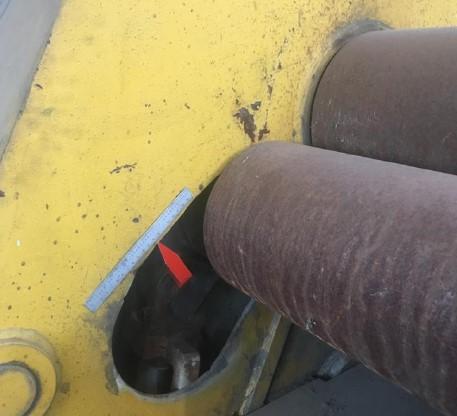
FIGURE 1 Before digital readouts, operators would measure the position of the lower rolls manually.
For instance, it is possible to develop a laser-based measurement device on both sides of the machine. The part is rolled completing the pass. The device measures the diameter or radius and feeds this measurement back to the control. The control compares the actual measurement to the measurement the control thinks it should have. Any correction is made for the next pass and continues the process until the final part dimensions are achieved.
For example, if on the first pass the machine sees it’s rolling a 40-in. diameter, and it knows the diameter needs to be 36 in., the machine’s algorithms—using the known material properties such as thickness and yield strength—will make the necessary adjustments for the next pass. Such extreme forms of real-time measurement are rare, simply because of the time and money involved. But it at least shows what pushing the envelope can achieve.
Cones and the CNC
The CNC can perfectly store settings for roll positions, linear travel, and the position at each end of each lower roll, if properly equipped. So if you can place the properly cut plate in the machine in the correct position, it should “theoretically” roll the part with the setting from the properly, previously rolled part.
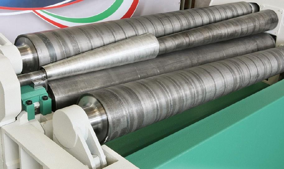
The only problem is that since the cone had two different diameters, the material must slide on the rolls; that is, you must pass the small end close to the cone attachment through at a slower rate than the big diameter. If the plate loses the “0” position, it cannot achieve consistent results cone to cone. Depending on what is being rolled and the quantities that justify the investment, tapered rolls can sometimes help (see Figure 6).
Manufacturers have not perfected the needed software and related machine components to consistently roll a cone, especially with the CNC finding the settings. Different factors, and factors in different ways than in the normal cylinder-type rolling, affects the final results. They include plate placement before rolling begins, tilt of the rolls, temperature of the plate, dirt on the plate and the location, slag on the material from plasma cutting, and different hardness locations from laser or plasma cutting.
Next-level Productivity
Modern rolling machines now can be part of larger automated systems that can incorporate feed systems, combination cut-to-length and feed systems, part loading, part ejection, special top support devices, even robotic part handling and part welding. All this offers fabricators ever greater levels of productivity.
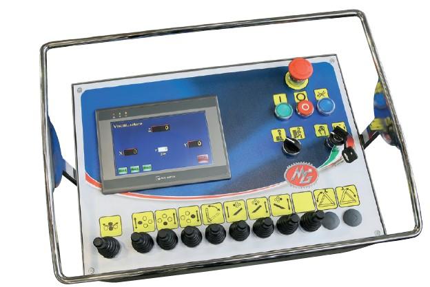
And when programming manually, a camera system can help operators locate the plate as close as possible to the center distance between the top and middle-bottom roll (see lead image). Plate rolling equipment-makers and service providers can even access the control remotely to provide customer support, and safety interlocks can be provided for applications as warranted.
New Opportunities in Rolling
Consider an operation that makes excavator buckets. The operation might bump them on the press brake, but doing so requires careful planning and handling. And no matter how well the brake performs incremental bending, in most conventional applications the brake will probably leave noticeable bend lines.
CNC rolling leaves no bend lines and can produce a better-looking product overall. And the intelligent CNC makes producing those buckets—along with square tanks, ellipses, ovals, and other products that require a true blended radius—much faster than it used to be. Moreover, CNCs can benefit training. By working on a CNC roll and observing the process, inexperienced operators learn more about rolling.
As with most machine tools, CNC rolling systems can help you achieve certain goals, but adjustments might have to be made to produce perfect results. Regardless, when you get those adjustments right, the CNC roll can help reduce your cost per part and, in many cases, dramatically shorten your production time.
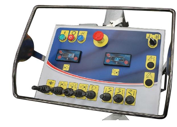
FIGURE 2 Digital readouts made for easy measuring of lineal travel.
Links to Illustrative Plate Rolling Videos
Two-roll bending machine with PLC
Two-roll bending machine example
Variable-radius bending, ellipse
Four-roll automation with a protection cage
Four-roll machine with robot loading system
CNC plate rolling with vertical supports
About the Author
About the Publication

subscribe now

The Fabricator is North America's leading magazine for the metal forming and fabricating industry. The magazine delivers the news, technical articles, and case histories that enable fabricators to do their jobs more efficiently. The Fabricator has served the industry since 1970.
start your free subscription- Stay connected from anywhere

Easily access valuable industry resources now with full access to the digital edition of The Fabricator.

Easily access valuable industry resources now with full access to the digital edition of The Welder.

Easily access valuable industry resources now with full access to the digital edition of The Tube and Pipe Journal.

Easily access valuable industry resources now with full access to the digital edition of The Fabricator en Español.
- Podcasting

In this episode of The Fabricator Podcast, Caleb Chamberlain, co-founder and CEO of OSH Cut, discusses his company’s...
- Trending Articles
1
Tips for creating sheet metal tubes with perforations

2
Supporting the metal fabricating industry through FMA

3
JM Steel triples capacity for solar energy projects at Pennsylvania facility

4
Are two heads better than one in fiber laser cutting?

5
Fabricating favorite childhood memories
