


Try out, debug dies on-screen
Why not let the computer find the mistakes?
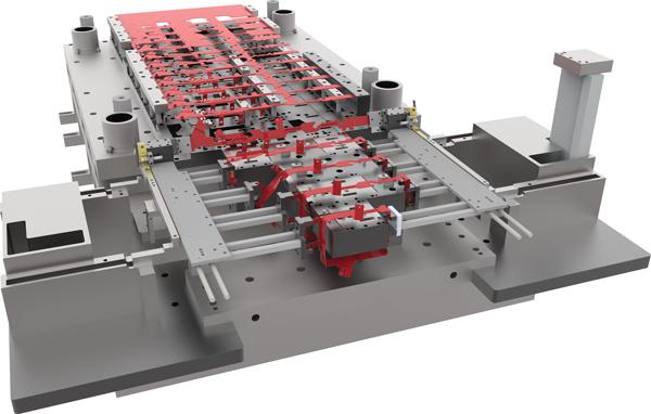
Traditionally, before a new stamping is launched, a die is designed, then built, and finally put into a tryout press in order to try out and debug the die. The goal of every die designer and die builder is to put a new die in the press and have the strip (or in the case of a transfer die, the blank) run all the way through the die and get a part out the end the first time it goes in the press. While this is the goal, the reality is, humans make mistakes, and mistakes are often found both as the new die is being assembled and when the die is tried out in the tryout press.
For example, a typical mistake found as the die is being assembled is that a counterbored hole for a socket head cap screw in a die block does not match the size of or does not line up with the corresponding tapped hole in the die shoe. Once the die is finally assembled and goes into the tryout press, strip feeding problems are often discovered (see Figure 1) and clearance issues are often found.
Tryout and Debugging Software
The ability to have a virtual press to try out and debug stamping dies on the computer screen represents a significant paradigm shift in die building and die tryout. Adding motion to the die as it is being designed, along with the use of dynamic interference detection at this stage, results in a less expensive and more profitable die that is delivered more quickly.
Recognizing these facts, a few companies have created software for trying out and debugging dies on the computer screen before the die is built, and some have integrated it into their die design software. While animation tools that allow all CAD users to add motion to their generic designs have existed for decades in mainstream 3D CAD modeling software, generally these generic tools have been found to be both incomplete for and too difficult to apply to stamping die designs.
Stamping dies and related tooling have unique motions, and once companies started to create software with these specific motions in mind, efficient tools gradually matured into the software that we have today.
Motions Found in Dies and Tooling
The various motions found in different tooling such as progressive dies, transfer dies, fourslide machines, vertical slide machines, and so forth are all similar. While some of the tryout and debugging software that is available focuses on and specializes in a specific type of tooling, other tryout and debugging software can be applied to the entire range of tooling used in the stamping industry.
There are four common motions that take place in most dies that now can be simulated in advanced die design software:
The first common motion within a die is the up-and-down motion of the press ram. The ram motion has evolved to include not only a traditional crank press, but also servo presses, for example.
The second common motion is the feeding of the material, typically known as the pitch or the progression. While progressive dies almost always have a single progression value, a transfer die more commonly has two different progressions in it: a shorter progression to make the flat blank and a longer progression after that to allow extra room for the forming stations.
The third common motion is the strip lift in the case of a progressive die, and the part lift for a transfer die.
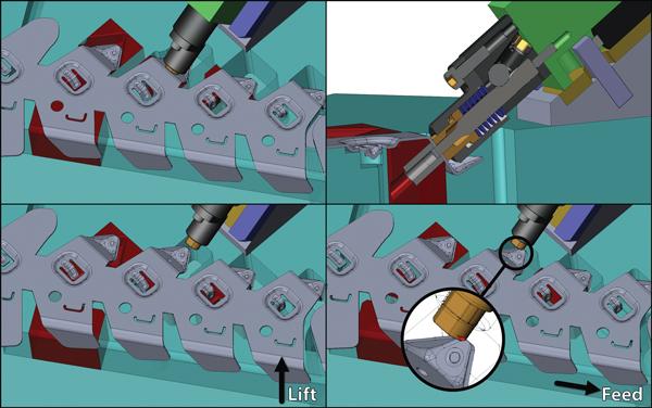
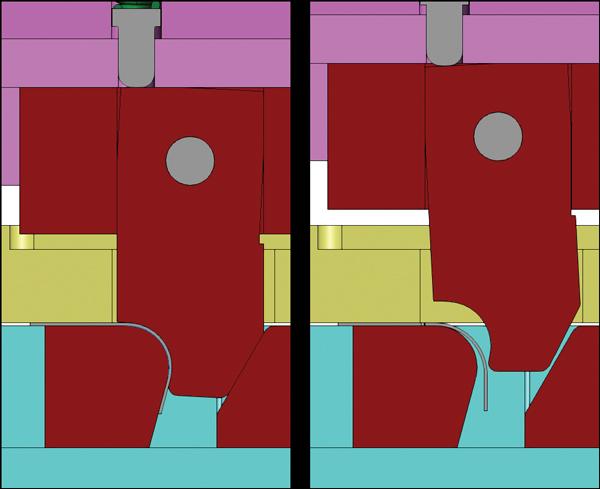
Figure 1
The top two images show the die in the closed, or “as designed,” state. The lower left image shows the die in the fully opened state within the die design software, and with the strip lifted. The lower right image shows the lifted strip starting to feed to the next station, during which the software detects a collision.The fourth common motion found in most dies is the stripper travel.

A less common motion found in some dies and tooling is cam motion. Some cams have a rotational eccentric motion such as is found on fourslide machines, and these cams are used in conjunction with cam followers in order to drive the slides in the fourslide machines (see Figure 2).
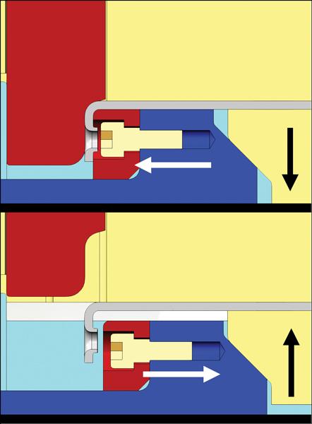
Other cams do not follow a unique path but simply move along a straight axis that is either horizontal or at some angle off horizontal. These include cam pierce units, cam forming units, and cam releases. Cam releases are used to release a part that is otherwise trapped after a forming process, which would prevent the part from lifting or feeding (see Figure 3).
Another motion that software needs to duplicate is a rotational motion, such as is found on a rocker form, for example. A rocker form is sometimes used when material needs to be overbent past 90 degrees to allow for springback (see Figure 4).
Die Shop’s Case Example
Before releasing a tool design to the shop floor, Oldenburg Metal Tech, Saukville, Wis., requires that the die motion has been simulated to duplicate what will happen in the press, and that dynamic interference detection has been checked during this motion simulation. While some people might think that this virtual die tryout adds extra time to a die design, Oldenburg Tooling Engineer Matt Bunkelmann said this is not the case and that, in fact, the opposite is true.
“It takes us less time to design a die using the specialized tools in our die design software for putting the die in motion than it used to take us before we had these tools,” Bunkelmann said. “This is because trying to put the die in motion prior to having these new capabilities—or even trying to show the die in various open positions in order to approximate the motion—required adding extra reference geometry to the design. The new motion simulation tools that we use today are made specifically for adding motion to the components that we have already created in order to make them move exactly as they will in the physical press. Adding this motion to a group of existing components using these specialized tools usually takes only a few minutes.”
Oldenburg Engineering Manager Mike Schmit said, “Since moving the die tryout from the press to the computer screen, we have greatly reduced both the mistakes that we used to find as the die was getting assembled, as well as the time we used to spend in and out of the tryout press finding and correcting mistakes.”
Die Design Firm’s Case Example
Tom Roth of Trademark Tool Designs LLC, Janesville, Wis., said, “As an independent die design company, I feel like we are held to a higher standard than in-house die designers. Customers don’t want to see any mistakes on their die designs. Having tools in our die design software that let us try out and debug the dies while we are still working on the die design is important to us.”
Fellow die designer Nick Roth likes the tools in the software that allow him to add motion to components easily by linking the motion of those components to other components in the die without having to enter any numbers. This is done by selecting the strip lift option from a drop-down list within the software that includes the existing motions available for the user to link to.
Roth said, “I like the fact that I can select one of my lifters, then select the filter that selects all of the lifters, and click the option called “Link to strip lift” in the software. I also find it especially useful that when the software gets done finding the interferences in a die, it puts them into a list and you can click on any one of these interferences to show only the two components that are interfering with one another, along with showing the interfering area in red. You can set various viewing options so that, for example, those two interfering components are the only things visible on the screen, along with the red interfering portion. In addition, you also see the rest of the model around them in wireframe so that you can easily see the environment where these components are located [see Figure 1].”
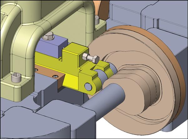
Figure 2
The cylindrical cam followers track around the path of the rotating eccentric cam, which in turn drives the motion of the horizontal slide in the fourslide machine.
Benefits of Tryout and Debugging Software
The use of the tryout and debugging software which is integrated into the die design software allows the die design to go faster and more smoothly than it would without the software. When it is used during the die design process, there are typically no problems assembling the die. Also, the tryout press should not be needed to find mechanical design mistakes, but only to get a part out the end of the die. Then the part can be inspected, and tweaks can be made to the forms and to the trim lines of the part as needed.
Letting the software check for mistakes frees up a design checker who normally would have done this after the design was complete. It also frees up the die designers from having to make changes to the design to fix any possible mistakes and frees up the tool- and diemakers from having to find these mistakes and remanufacture or make changes to the components. Finally, less time is spent in the tryout press, which, in some cases, is a much more valuable production press that needs to be temporarily used for this die tryout.
As the workforce of experienced die designers matures and enters retirement age, multiple problems are occurring. One of these problems is that companies find themselves needing to train people as new die designers who have virtually no die design or diemaking experience.
The tryout and debugging aspects of this new software allow new designers to catch mistakes earlier and more easily than they otherwise would. A major benefit to tryout and debugging software is that it also helps these new designers and their mentors to visualize the design much more easily because the die (or tool) is moving as it will move in the press, subsequently bringing the new designers up to speed much more quickly than otherwise possible.
Ray Proeber is president of Accurate Die Design Software Inc., 200 S. Executive Drive, Suite 101, Brookfield, WI 53005, 262-938-9316, ray.proeber@diedesignsoftware.com, www.diedesignsoftware.com.
About the Author
About the Publication

subscribe now

The Fabricator is North America's leading magazine for the metal forming and fabricating industry. The magazine delivers the news, technical articles, and case histories that enable fabricators to do their jobs more efficiently. The Fabricator has served the industry since 1970.
start your free subscription- Stay connected from anywhere

Easily access valuable industry resources now with full access to the digital edition of The Fabricator.

Easily access valuable industry resources now with full access to the digital edition of The Welder.

Easily access valuable industry resources now with full access to the digital edition of The Tube and Pipe Journal.

Easily access valuable industry resources now with full access to the digital edition of The Fabricator en Español.
- Podcasting

In this episode of The Fabricator Podcast, Caleb Chamberlain, co-founder and CEO of OSH Cut, discusses his company’s...
- Trending Articles
1
Tips for creating sheet metal tubes with perforations

2
Are two heads better than one in fiber laser cutting?

3
Supporting the metal fabricating industry through FMA

4
JM Steel triples capacity for solar energy projects at Pennsylvania facility

5
Omco Solar opens second Alabama manufacturing facility
