


Research Engineer, Manufacturing and Metals Research
z1b / iStock / Getty Images Plus
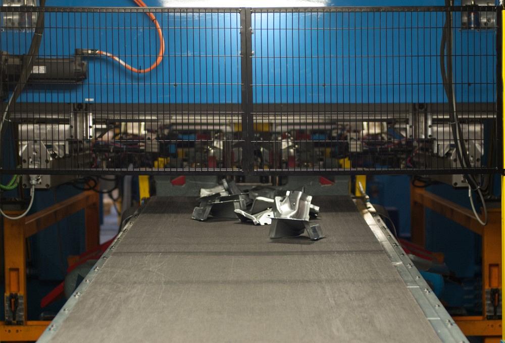
With the transportation industry’s current trend toward reducing both vehicle weight and overall raw material consumption, more manufacturing suppliers are stamping lightweight materials, particularly aluminum alloys. It’s important for these manufacturers to understand the performance of the punching inserts they use on these materials.
Since the loads on the edges of punching inserts are typically the highest within stamping operations and significantly exceed the flow stress of the sheared sheet, these tools potentially undergo more wear than other parts of the stamping dies. And worn tooling can cause burrs on the edges of stamped parts, particles of stamped sheet spreading through the surfaces of stamping dies, and edge splitting on stamped components where the sheared edge has stretched.
Manufacturers need to understand the possible failure modes and identify the combinations of die materials and surface treatments that work well in stamping production and minimize degradation of punching inserts.
Researchers at the Oakland University Center of Advanced Manufacturing and Materials recently investigated the behavior of punching inserts in stamping of aluminum alloy sheet AA5754, typically used for lightweight automotive structural parts. They compared uncoated M2 inserts to M2 inserts coated with Ionbond 42 (Cr + CrN + a-C:H:W + a-C:H), ZrN, Tetrabond Plus (ta-C), and Tetrabond (ta-C). This study employed the U-bend stamping process, which included both shearing and stretch bending operations and allowed the researchers to study performance of punching and forming inserts.
The design of the progressive die used to stamp the U-bend coupons is illustrated in Figure 1 and explained in “Detecting the onset of galling in aluminum sheet stamping.” Portions of the perimeter were blanked sequentially out of the coil material while it flowed through the progressive die; then drawing inserts were used to cut the last portion of the edge and form the U-bend part.
Punching inserts fabricated from M2 tool steel were used to cut four different areas of the perimeter. With this approach, four different punching insert configurations were studied simultaneously and named based on their right- or left-hand location: LH-out, LH-in, RH-in, and RH-out.
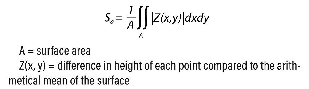
To understand the changes occurring on the punch surface, the researchers measured the roughness of the inserts before and after testing using a Bruker model ContourGT-K optical noncontact profiling system. Measurements were processed with Bruker Vision64 software. Roughness was calculated as Sa value, which is an absolute value of the difference in height of each point compared to the arithmetical mean of the surface, using the equation in Figure 2.
After the test, surface roughness was measured in the area of visible wear. The roughness was reported for the roughest area of the punching inserts correlating with the total number of parts stamped using each of the studied inserts.
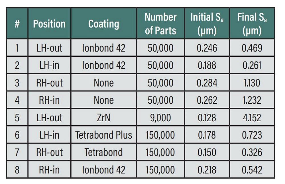
Inserts were tested in groups: right-out, right-in, left-out, and left-in. Figure 3 provides a list of testing combinations and the number of parts produced with these inserts.
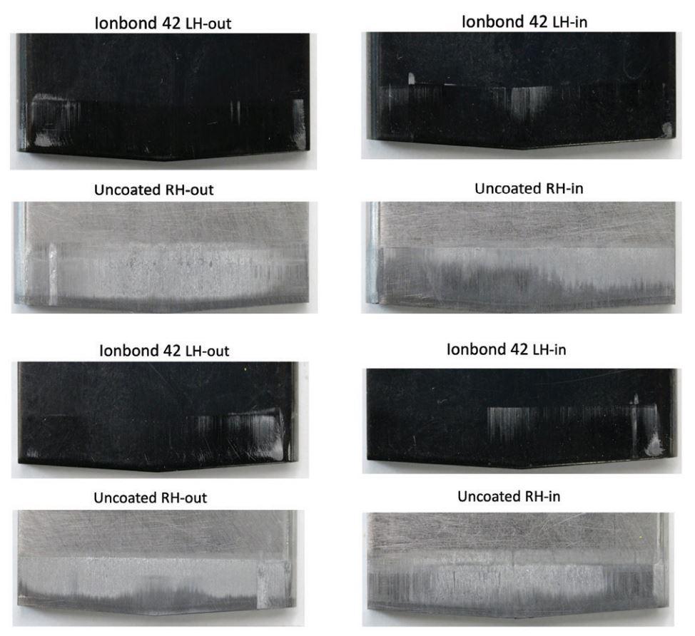
Inserts 1 to 4 were used to stamp 50,000 U-bend parts. Surface roughness was observed on the coated inserts, but it increased by more than a factor of four on the noncoated inserts. Images of punching inserts 1 to 4 after the 50,000 stamped parts are shown in Figure 4 from both sides of the punch. The uncoated inserts show signs of galling formation.
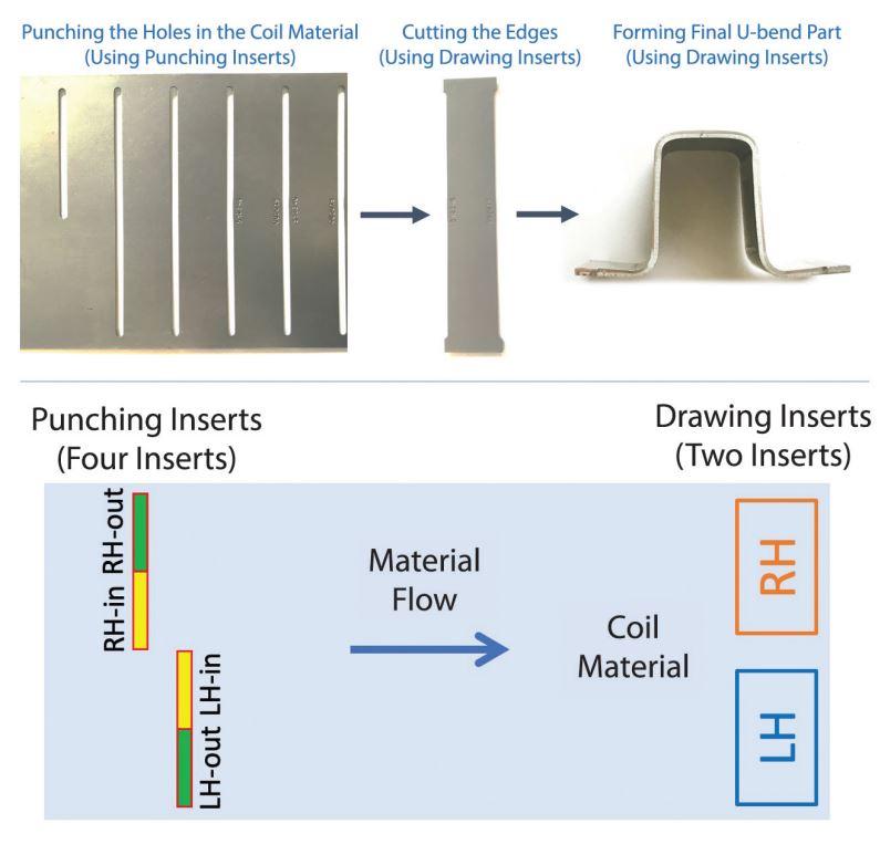
FIGURE 1. This is a schematic of the progressive die used to stamp the U-bond coupons.
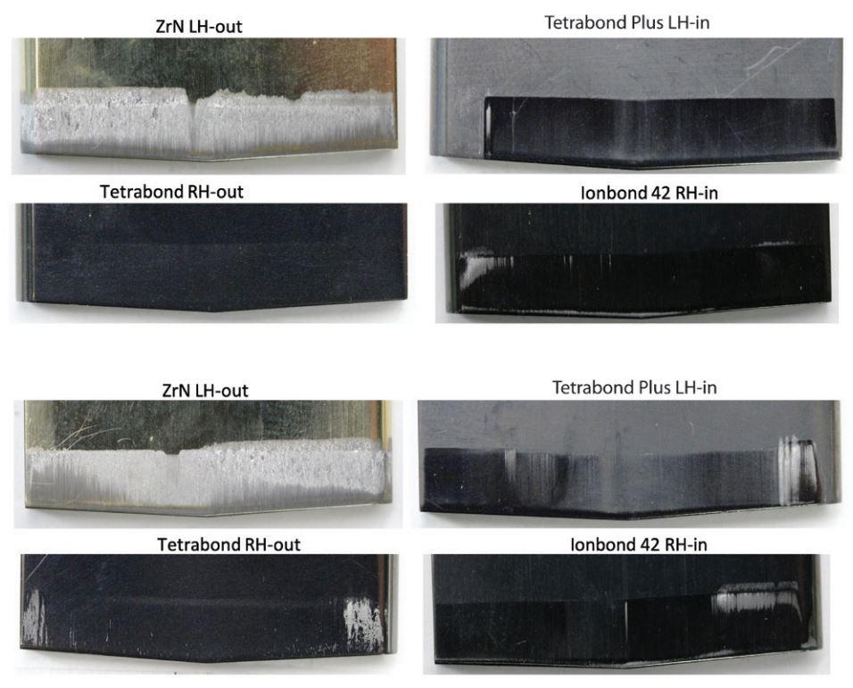
Insert 5 (ZrN) was used to stamp only 9,000 parts. Its roughness increased substantially, and it showed significant signs of galling on both sides. Inserts 6 to 8 (Tetrabond Plus, Tetrabond, and Ionbond 42) each were used to stamp 150,000 parts. They showed a lower roughness increase than the uncoated punches used to stamp 50,000 parts. Figure 5 shows punching inserts 5 to 8 after stamping, from both sides of each punch.
Based upon their comparison of surface roughness on punch inserts before and after shearing the perimeter of 2.5-mm-thick AA5754 parts, the researchers concluded that the wear performance of the punching inserts coated with Ionbond 42, Tetrabond, and Tetrabond Plus was superior to that of the uncoated punching inserts. These coated inserts had no significant visual signs of wear or galling and a rather moderate increase of surface roughness after 150,000 stamping cycles.
They also determined that ZrN coating is not appropriate for punching AA5754 aluminum alloy sheet, as the coated punch showed significant galling and changes in surface roughness after 9,000 stamping cycles.
This research project was funded in part by the United States Council for Automotive Research with contributions from Novelis Corp., which provided 5754 aluminum alloy coil; Moeller Precision Tool Co., which fabricated all the punching inserts for this study; and Ionbond LLC, which provided coating of the tested inserts.

Professor and Director
Oakland University Center of Advanced Manufacturing and Materials (CAMM)

PhD Candidate
Oakland University Center of Advanced Manufacturing and Materials (CAMM)


The Fabricator is North America's leading magazine for the metal forming and fabricating industry. The magazine delivers the news, technical articles, and case histories that enable fabricators to do their jobs more efficiently. The Fabricator has served the industry since 1970.
start your free subscription
Easily access valuable industry resources now with full access to the digital edition of The Fabricator.

Easily access valuable industry resources now with full access to the digital edition of The Welder.

Easily access valuable industry resources now with full access to the digital edition of The Tube and Pipe Journal.

Easily access valuable industry resources now with full access to the digital edition of The Fabricator en Español.
In this episode of The Fabricator Podcast, Caleb Chamberlain, co-founder and CEO of OSH Cut, discusses his company’s...


