Contributing Writer
- FMA
- The Fabricator
- FABTECH
- Canadian Metalworking
Categories
- Additive Manufacturing
- Aluminum Welding
- Arc Welding
- Assembly and Joining
- Automation and Robotics
- Bending and Forming
- Consumables
- Cutting and Weld Prep
- Electric Vehicles
- En Español
- Finishing
- Hydroforming
- Laser Cutting
- Laser Welding
- Machining
- Manufacturing Software
- Materials Handling
- Metals/Materials
- Oxyfuel Cutting
- Plasma Cutting
- Power Tools
- Punching and Other Holemaking
- Roll Forming
- Safety
- Sawing
- Shearing
- Shop Management
- Testing and Measuring
- Tube and Pipe Fabrication
- Tube and Pipe Production
- Waterjet Cutting
Industry Directory
Webcasts
Podcasts
FAB 40
Advertise
Subscribe
Account Login
Search
3D modeling for step-by-step instructions
CAD programmers can prepare illustrations using display states and exploded views
- By Gerald Davis
- January 31, 2020
- Article
- Manufacturing Software
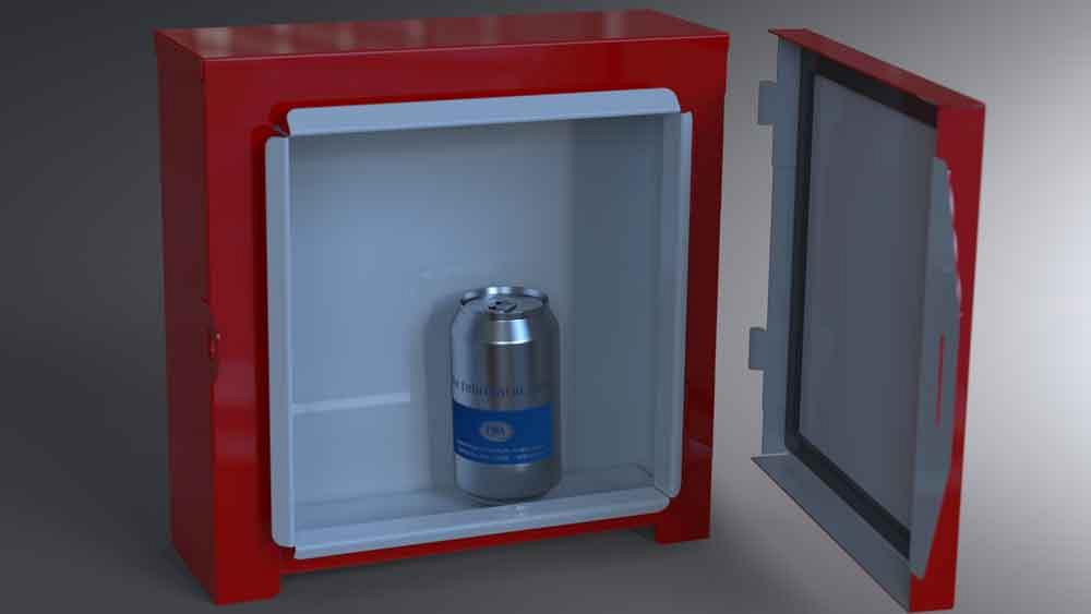
Figure 1b
The door is an assembly of socket hinge leaves, sheet metal, and gasket tape. The box is an assembly with pin leaves and several pieces of sheet metal.
Editor's Note: If you would like to download the 3-D CAD files associated with this column, click here.
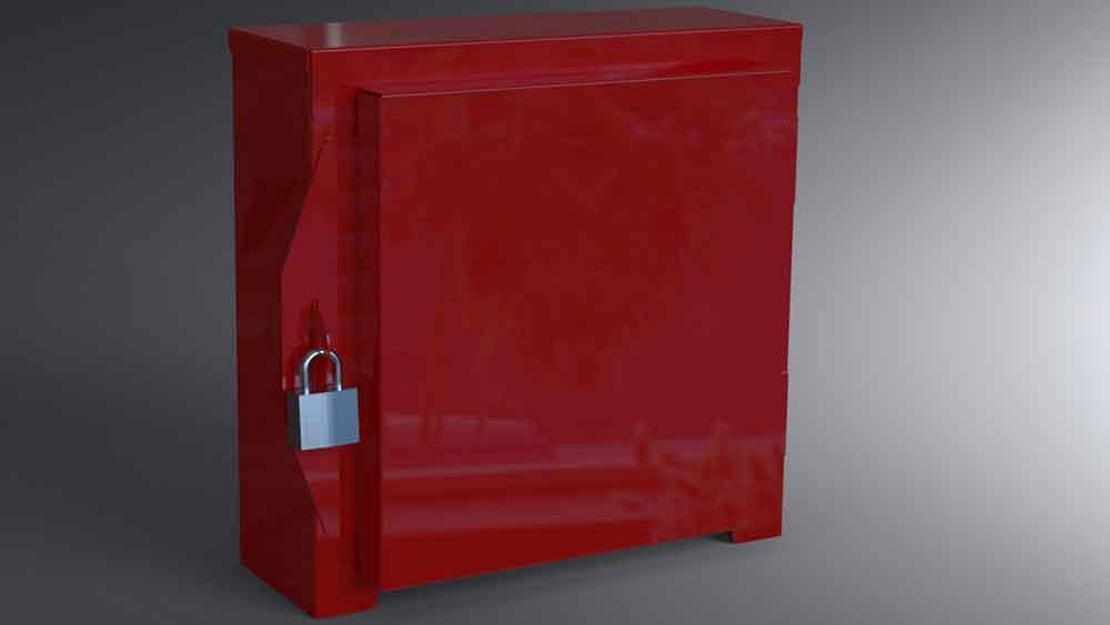
A hinged box (see Figure 1a) was introduced in my previous column. In CAD-speak, this product is modeled as a top-level assembly with two subcomponents, a door subassembly and a box subassembly. The door assembly includes a weldment of socket hinges to sheet metal along with paint and a gasket. The box is a weldment with the pin hinges followed by paint.
As modeled for live presentation, the door can swing zero to 90 degrees relative to the box. The mouse can be used to drag the door’s position. That range of motion is permitted only in the “Closed” configuration. The “Open” configuration locks the door position to be perpendicular to the box. No mouse dragging is needed in the latter configuration.
The two-piece hinge allows the gasketed door to be removed as shown in Figure 1b. The CAD task at hand is to document this welded sheet metal box for fabrication.
Disclaimer: The padlock and pop-top can are not part of the product. They are just shown for visual scaling. We offer a download of these CAD files and are not aware of any patent or claim of intellectual property on this design.
Frequent readers of this column have encountered the acronym PMI, product manufacturing information. As used in this hinged example, PMI is the information about the component that is not 3D—for example, text for part number-revision, description, finish, tolerance, supplier, part marking, and packing requirements. With the mainstream 3D CAD software being employed, bill of material (BOM) tables and drawings can display any or all of the PMI held by the components in the drawing’s view.
Step-by-stepping in the Assembly
The task is to prepare illustrated step-by-step instructions. Before the drawing view can be set up, our hinged box, also known as the product, must have display states and exploded views ready to go.
In preparation for making the illustrations, the top-level assembly is dolled up with more than eight exploded views and corresponding display states (see Figure 1c). These display states are named to indicate what they show/hide, which makes them user-friendly when the CAD jockey is subsequently setting up a drawing view. Also, the exploded views are named to indicate which components they position.
The plan for the 2D drawing is to use balloons to identify the items being assembled. Balloons have their item numbers assigned to them from a BOM table.
The BOM table is set to self-assign item numbers to rows and thus to the item numbers shown in balloons. If the list of items in the BOM changes, the item numbers, balloons, and quantities required automatically update.
The two-piece hinge in Figure 1b presents a bit of a challenge to automatic item numbering and counting. Each hinge has two visible bodies, but only one of them should be counted by the BOM table.
The auto-item-balloon trick for this episode is to use a configured hinge model. Here is a secret about the hinge model: It is configured with PMI in only one of its hinge-leaf bodies.
To avoid asterisks in balloons, we use careful aim. When annotating a view in a drawing, we attach balloons to visible bodies that are known to possess PMI, not to visible bodies that are known to have been excluded from the BOM.
View at Top of Chain of Command
A setting that can be useful in this exercise links display state to configuration, which causes the display state to automatically change when the configuration changes. We don’t want that for this demonstration, however. Unchecked, the display state is not linked to the configuration. In our scenario, the drawing view selects the display state that it wants.
Because display states can’t position components and our scenario requires that components be positioned, the demonstrated CAD trick is to use several Exploded View features to position components as needed. One of those exploded views lifted the door off of the hinges in Figure 1b.
Setting a BOM Table
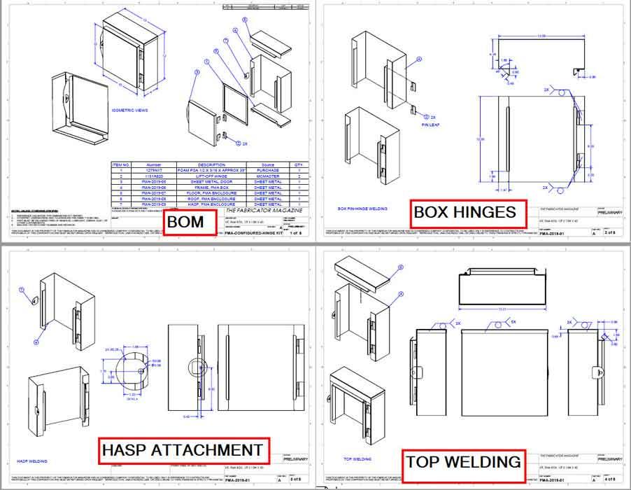
The first four sheets of the eight-sheet drawing for this episode appear in Figure 2a. Each view on each sheet is showing different combinations and positions of parts and their identifying balloons.
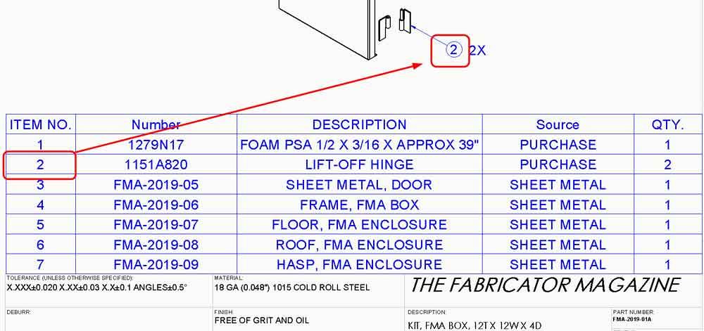
As mentioned earlier, this product is modeled as an assembly made up of subassemblies. Figure 2b shows a closeup of the BOM table that assigns item numbers to our balloons. Item 2 is the hinge, a quantity of two of them is needed. You may note that this table does not show the hierarchy of subassemblies. That is a design choice for this drawing.
If the door was manufactured on a different production line from the box, then a different kind of BOM table organization could be preferred. That is an easy setting for the BOM table.
In this scenario, all of the fabrication happens as a single event, so a single multisheet drawing suits our production line nicely.
The BOM table in Figure 2b is using a CAD setting that shows only the parts, not subassemblies that contain the parts. Again, this is a design choice based on the documentation requirements of the production line.
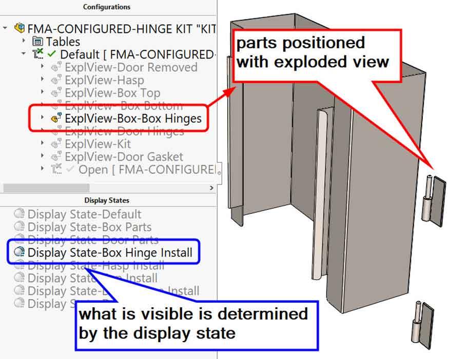
Figure 1c
The assembly has more than eight exploded views and corresponding display states to support the step-by-step illustrations. Here we see a setup to show the hinges removed from the box. It is up to the view in the drawing to select the appropriate combination to position and hide/show the desired items.
Seeding A Priori
While being clever with the CAD tricks, we want to be kind to those in sustaining engineering. Things are obvious if you know about them. As thoughtful CAD jockeys, we aspire to use methods that are standard to our place of employment. When no other consideration prevails, likely-to be-known by the next editor of the CAD file works as a policy.
With the mainstream 3D CAD being discussed, views in drawings have settings for the selection of a component’s configuration, possibly its exploded position, and a display state. The ability to explode is up to the component; to explode (or not) is up to the view.
Why not just hide the part in the drawing view instead of using display states in the component? Drawing views possess the ability to hide or show components on their own, separately from the display states in the component. In situations where a drawing view hides components on its own, the next CAD jockey up will need to discover how hide/show was done.
That discovery is not so difficult. The answer hides in the drawing’s Feature Manager. Find the sheet, find the drawing view, completely expand the view’s components, and the hidden items will be low-lighted.
For our purposes, display states are doubly useful. In live presentations the display states switch very quickly on almost any computer. Perhaps more importantly, display states are easy to edit.
If the next CAD jockey to edit the file has read this article, he or she will find the display state technique to be intuitive. Here, intuitive technique means that the CAD jockey manually selects the display state of the sheet metal box for instructional viewing.
View With a Lovely Setting
The work flow for creating each view in this drawing was approximately the same—create a view, position the assembly, and then adjust the view’s settings to select a display state and an exploded view.
Figure 2c shows the remaining four sheets of our drawing. The three steps for installing the door onto the box are shown on the last sheet of the drawing, seen in the bottom right corner of Figure 2c.
Here is how to install the door in three steps:
- With the door open, position it over the hinges on the box.
Slide the hinges together.
Close the door and snap the hasp.
All three of these views are using the same display state to show all of the parts in this product. Compare that to the door assembly view shown at the bottom left of Figure 2c. The same configuration is used there, but a different display state causes everything except the door parts to be hidden.
The view for door install described in step 1 is using the Open configuration to mate the door perpendicular to the box. This view also uses an exploded view named Door Removed to lift it away from the box.
The view for door install in step 2 turns off the exploded option, thus sliding the hinges together but keeping the door open. The view for step 3 closes the door by changing configurations from Open to Closed.
Gerald would love for you to send him your comments and questions. You are not alone, and the problems you face often are shared by others. Send your questions and comments to dand@thefabricator.com.
About the Author
subscribe now

The Fabricator is North America's leading magazine for the metal forming and fabricating industry. The magazine delivers the news, technical articles, and case histories that enable fabricators to do their jobs more efficiently. The Fabricator has served the industry since 1970.
start your free subscription- Stay connected from anywhere

Easily access valuable industry resources now with full access to the digital edition of The Fabricator.

Easily access valuable industry resources now with full access to the digital edition of The Welder.

Easily access valuable industry resources now with full access to the digital edition of The Tube and Pipe Journal.
- Podcasting
- Podcast:
- The Fabricator Podcast
- Published:
- 04/30/2024
- Running Time:
- 53:00
Seth Feldman of Iowa-based Wertzbaugher Services joins The Fabricator Podcast to offer his take as a Gen Zer...
- Trending Articles
JM Steel triples capacity for solar energy projects at Pennsylvania facility

Fabricating favorite childhood memories

How laser and TIG welding coexist in the modern job shop

Robotic welding sets up small-batch manufacturer for future growth
Ultra Tool and Manufacturing adds 2D laser system
- Industry Events
Pipe and Tube Conference
- May 21 - 22, 2024
- Omaha, NE
World-Class Roll Forming Workshop
- June 5 - 6, 2024
- Louisville, KY
Advanced Laser Application Workshop
- June 25 - 27, 2024
- Novi, MI
Precision Press Brake Certificate Course
- July 31 - August 1, 2024
- Elgin,

