


Contributing Writer

An overview of the ASME Y14.000 standard discusses different types of drawings, lists, and tables. Getty Images
Editor's Note: If you would like to download the 3-D CAD files associated with this column, click here.
Old guys like me remember when DOD-STD-100 was developed to coordinate the engineering drafting standards for the U.S. Department of Defense. Well, maybe I’m not that old. The civilian version of the standard evolved through MIL-STD-100 and subsequent ANSI standards to become today’s ASME Y14.100, Engineering Drawing Practices.
Many brands of CAD software feature tools to standardize drafting practice. Additionally, mainstream 3D CAD software ships with drawing templates that have borders, title blocks, tables, and document control features designed for compliance with ANSI, ISO, and other drafting standards.
The forward for ASME Y14.100-2004 page IV explains that it is a composite set of standards (specifically ASME Y14.24, Types and Applications of Engineering Drawings, ASME Y14.34, Associated Lists, and ASME Y14.35, Revision of Engineering Drawings and Associated Documents). These documents represent a guide as opposed to a rigid set of rules. To quote from the forward to ASME 14.100, “It is well recognized that individual companies have many detailed requirements for their specific method of operation.” Thus, a blessing to customize the templates to suit any company’s standard.
In the era before CAD, extensive human labor was applied to each drawing. Teams of people trained for specialized careers in different types of drawings. To coordinate this labor, roughly a dozen types of engineering drawings are described in ASME Y14.24M-1989.
Modern 3D CAD makes it practical (and typical business practice makes it desirable) to combine and overlap the various drawing types. When customizing templates for data entry, drawings, parts, and assemblies, it can be useful to review ASME Y14.24’s drawing types. The drawing’s content, the projected views, and the expected tables are examples of distinction between drawing types. Drawing types include layout, detail, assembly, installation, modifying, arrangement, control, mechanical schematic, electrical/electronic diagrams, special application, and ancillary.
Figure 1 is an example of an arrangement-type drawing for a grease gun. The range of motion for the handles, cartridge size, and nomenclature are indicated. Once the product is fabricated and assembled, the arrangement drawings address physical access, service, and operation of the device. Installation drawings address the structural, plumbing, and power.
The definitions of types are self-evident: They pretty much are what they sound like they should be. Ancillary drawings serve as a last resort, a miscellaneous vehicle if no other document type will do.
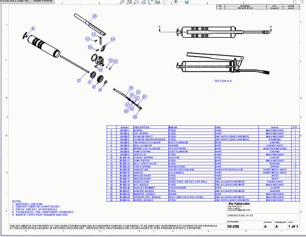
A modifying drawing is for an item made from bulk length material, such as a raw extrusion. The layout drawing is often used in research and development. Detail and assembly drawings provide complete end-product definition of the parts and how they go together. Figure 2 is an example of an assembly drawing that shows all of the components that go into a grease gun.
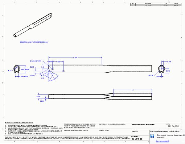
Figure 3 is an example of a detail drawing that shows how to make a grease gun handle. Detail drawings are typically what fabricators work with. The other drawing types (such as mechanical schematics and electronic diagrams, special application, and ancillary) are variations on the theme of a detail drawing.
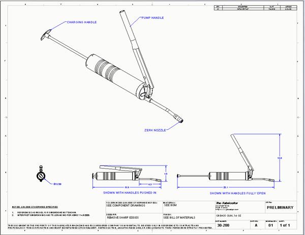
Figure 1
An example of an arrangement-type drawing for a grease gun is shown. This drawing type addresses physical access and other operational considerations.
Control drawings typically are not so much drawings as notes on detail drawings. These also can be prepared as stand-alone documents.
Glibly said, control drawings are cherished by the legal department. In the event that a CSI Las Vegas-type audit is required, the control drawings provide the procurement plan as well as the acceptance criteria, performance qualification, and certification for the product.
As with drawing types, various lists fall under the aegis of standard practice. ASME 14.34, Associated Lists, Engineering Drawing and Related Documentation Practices is an example of such a standard.
Things that might be listed include parts, applications, data, index, and wire. Lists may be integral (revised as part of the drawing) or separate (revised as a stand-alone document). Separate lists have identifying codes used as line item prefixes. Integral lists omit the identifying prefix.
A list simply presents information. All aspects of the presentation are considered. This includes the unit of measure—inch or metric—as well as the font and line style used to draw the table. The column widths and the location of the list should be consistent from drawing to drawing.
Sometimes the standards bend over backwards to be rigidly versatile. For example, the heading for a table should repeat across page breaks. But headings (or the lack of headings) can vary according to the needs of the preparing activity.
It may be noted that Figures 1, 2, and 3 show inconsistencies in title block, revision table, and notes. These are examples of a pending revision. A preliminary drawing may be changed without concern. Revision to a released drawing has consequences: Old revisions must be replaced wherever they have been distributed.
The previous column predicted that this episode would be about revision of engineering drawings, but an unexpected digression into drawing types has led us to predict that the next episode will dig into revision of drawings with ASME Y14.35 in mind.
Gerald would love for you to send him your comments and questions. You are not alone, and the problems you face often are shared by others. Share the grief, and perhaps we will all share in the joy of finding answers. Please send your questions and comments to dand@thefabricator.com.


The Fabricator is North America's leading magazine for the metal forming and fabricating industry. The magazine delivers the news, technical articles, and case histories that enable fabricators to do their jobs more efficiently. The Fabricator has served the industry since 1970.
start your free subscription
Easily access valuable industry resources now with full access to the digital edition of The Fabricator.

Easily access valuable industry resources now with full access to the digital edition of The Welder.

Easily access valuable industry resources now with full access to the digital edition of The Tube and Pipe Journal.

Easily access valuable industry resources now with full access to the digital edition of The Fabricator en Español.
Seth Feldman of Iowa-based Wertzbaugher Services joins The Fabricator Podcast to offer his take as a Gen Zer...


