


Contributing Writer
vm/Royalty-free/Getty Images
Several recent episodes of this column have discussed methods for speeding and standardizing the CAD jockey’s data entry chores. Selection lists, radio buttons, and check boxes have all been covered (see Figure 1). The general goal behind the data entry form is less typing and more productive modeling.
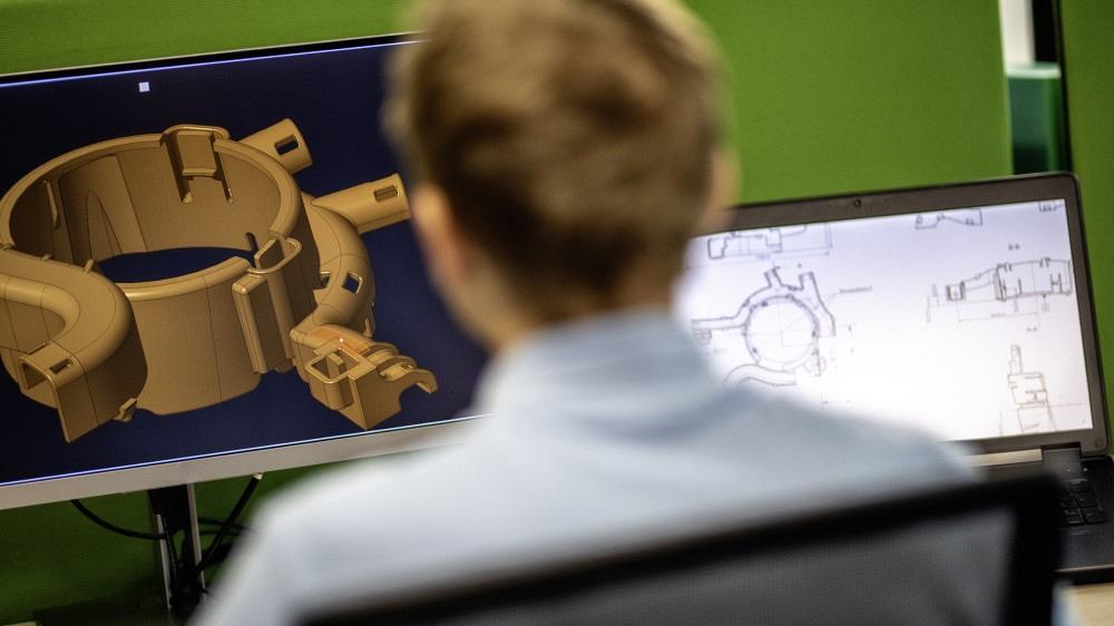
As a CAD project that will have a lifetime spanning many years, the FMA cart is something that you are now very familiar with (see Figure 2). The finished project likely will have dozens of drawings for manufacturing and assembly that will be revised by many hands.
Please note this disclaimer: The cart is a product in the sense that a CAD model of it exists. This product is imaginary in the sense that it is a DIY project, not for sale. It is used here for the discussion of CAD techniques.
An investment in designing templates and forms has quick payback in projects like this. A good combination of forms and templates standardizes and speeds the work.
The topic of tolerances in the February 2022 episode caught the attention of Mike Matusky in Everett, Wash. With his help, we incorporate some of his thoughts in the design of our templates and forms.
The drawings (PDFs) created for this project will be used to control the process of manufacturing—to let interested parties (including inspectors) know what is required. The drawings exist as part of a quality plan.
In this scenario we stipulate that our company standards exist within the aegis of a quality plan. This includes policy and procedure for specifying inspection equipment to be used, how it is to be set up, and what is to be recorded and calibrated. The quality plan controls drafting standards and is the guide for the design effort that goes into forms and templates. When it comes to drafting, geometric dimensioning and tolerancing (GD&T) is a key player in communication of accept/reject decision requirements.
A detailed quality plan and comprehensive training on GD&T are beyond the scope of this article. Both are recommended and important.
Matusky observed that CAD techniques for filling in information fields in title blocks are well-covered thus far. How the default tolerance appearing in the title block assures the usability of the finished product is a neglected and important topic.
To paraphrase Matusky’s imperative, adherence to ASME Y14.5 drafting standards and the proper use of GD&T can provide a path to less scrap, reject, and failure. Beware the perilous path of persisting in using toleranced (plus/minus) dimensions to locate, orient, and define the form of the part’s features.
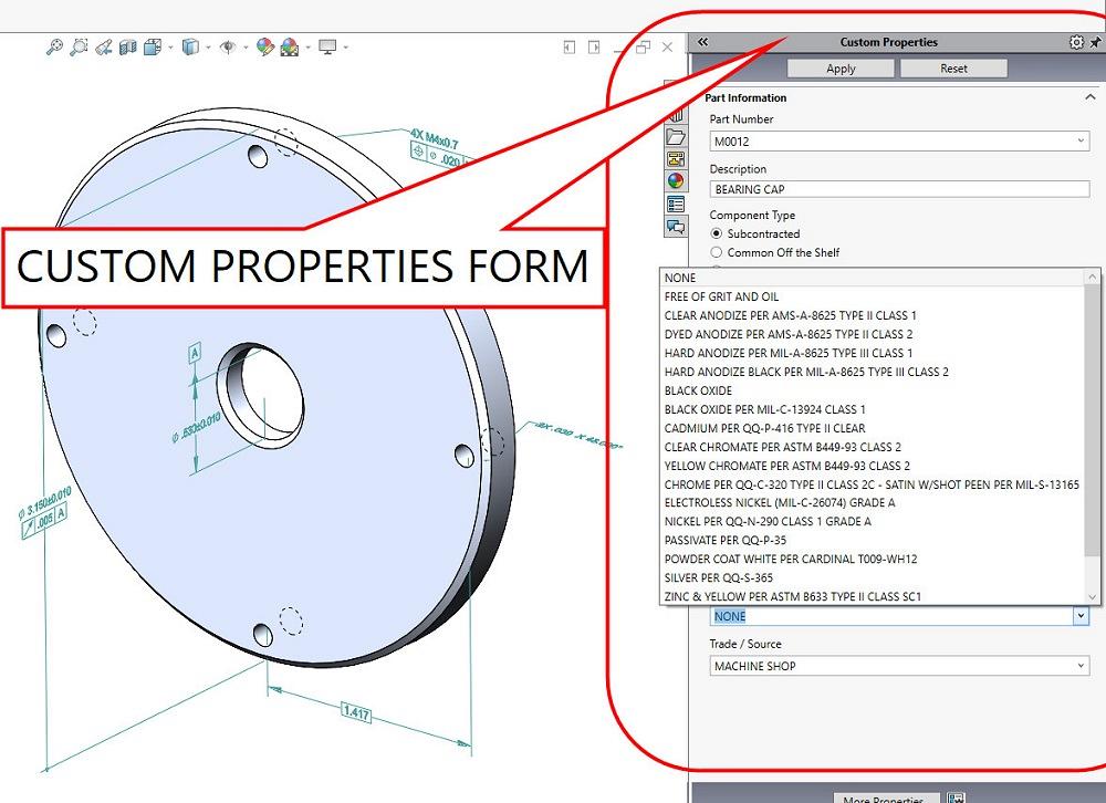
FIGURE 1. A data entry form is shown to the right. A drop-down selection list for finish is active. Selection lists reduce the amount of typing and creative writing.
Figure 3 is an example of a marginal company standard. This is a drawing for a sheet metal battery tray. The title block shows a default tolerance. The dimensions have their precision (number of digits) adjusted to indicate the acceptable tolerance.
Side note: The idea behind the default tolerance is to avoid having to add a tolerance to each drawing dimension. Another method is to declare in a standard note that untoleranced dimensions are basic. (Note that “basic dimension” has a very specific meaning in Y14.5.)
It is almost good in the sense that plus/minus dimensions are not always a bad drafting technique. Accept/reject decisions can be made reliably if the plus/minus feature can be contacted with the inside or outside jaws of a caliper in a manner that reflects the feature’s function. That is the case in Figure 3. The accept/reject measurements for these features are easy to attain.
On the other hand, if a coordinate measuring machine (CMM) or similar test gauge is required in the quality plan, GD&T is a good method for communicating the way to inspect the part.
Even if the part can be inspected with calipers, the company standard we’ve shown in Figure 3 is problematic.
Figure 3 echoes this company standard: A dimension shown with more decimal places means a tighter tolerance. In this instance, more precision is required. An example is “X.XXX ±0.020, X.XX ±0.05, X.X ±-0.3.”
This round-for-tolerance scheme is labor-saving for the CAD jockey. Simply increase or decrease the dimension’s digit count for more or less precision. While labor-saving from one perspective, this is not a victory for fabrication.
As an example of marginal result, the rounding of a three-place value (0.425 in., for example) introduces a discrepancy. The drawing shows 0.43 in. with ±0.05 in. as a default tolerance, whereas the STEP file shows the nominal value of 0.425 in. This puts inspection and CNC programming permanently at odds by 0.005 in.
As another problem, the tolerable size allowed (0.380 in. to 0.480 in.) might simply represent laziness, not function in terms of how the part is used.
And to further confuse things, nominal dimensions don’t always have symmetrical tolerance bands on the drawing. Is the 3D model to then show a limit, or should it be changed to average value? The answer is found in the quality plan.
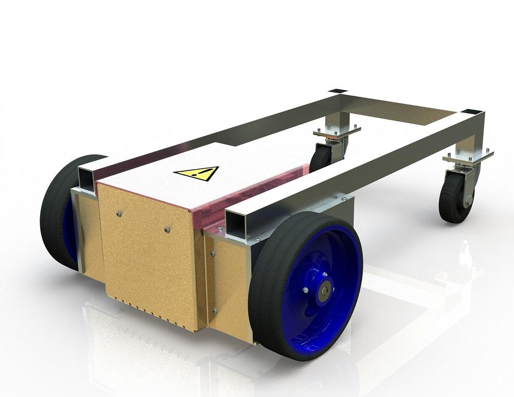
FIGURE 2. This product will require many drawings and probably will have several people working on it over time. As this new project is launched, the forms and templates are being designed to reduce labor and improve consistency.
To avoid such confusion, GD&T makes a distinction between tolerances for size, position, and profile, with position and profile measured relative to a datum reference frame (DRF).
Perhaps a better template design for the company-standard title block involves showing defaults for each type of tolerance. Matusky suggests that incorporating a little bit of GD&T into the company standard isn’t that painful and is likely to reduce the cost of fabrication because of higher yields and less time spent on inspection.
In the proposed GD&T-friendly company standard, the various default tolerances in the title block would apply to all features. These default tolerances would be established for ease of manufacturing. The default tolerances are trip wires to detect a process that is grossly malfunctioning.
Features needing tighter control would be called out on the drawing to override the defaults in the title block. As Matusky noted, such overriding notations automatically stand out. The routine inspection of only critical features not only saves time and money, but it’s also an achievable goal.
To quote Matusky, “The features that locate the part in the next assembly should be the same features that establish the default DRF.”
In this paradigm, the tolerances that are inspected relative a DRF are effectively inspected as the parts will be assembled. The DRF is a means to design the quality in instead of trying to inspect it in later.
A company standard for implementing GD&T should address how to select the datum features used to establish the DRF for the default tolerances. Features that locate the part should be designated as datum features.
Does a default tolerance belong in the title block? Would it be better to reduce the size of the title block (no default tolerance) or to expand the title block to show several types of tolerance? What notes lurk in the shadows of templates?
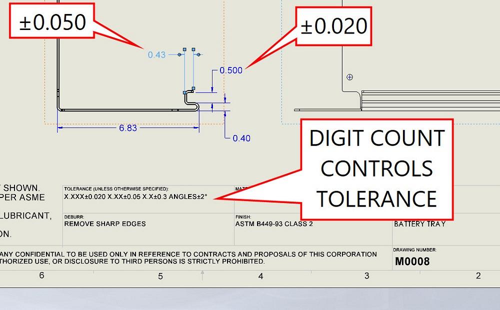
FIGURE 3. When the feature can be measured with the jaws of a caliper, an inclusion of plus/minus dimensions in the print gets the job done. The use of a digit count to indicate required precision can lead to confusion.


The Fabricator is North America's leading magazine for the metal forming and fabricating industry. The magazine delivers the news, technical articles, and case histories that enable fabricators to do their jobs more efficiently. The Fabricator has served the industry since 1970.
start your free subscription
Easily access valuable industry resources now with full access to the digital edition of The Fabricator.

Easily access valuable industry resources now with full access to the digital edition of The Welder.

Easily access valuable industry resources now with full access to the digital edition of The Tube and Pipe Journal.

Easily access valuable industry resources now with full access to the digital edition of The Fabricator en Español.
Seth Feldman of Iowa-based Wertzbaugher Services joins The Fabricator Podcast to offer his take as a Gen Zer...


