


Contributing Writer
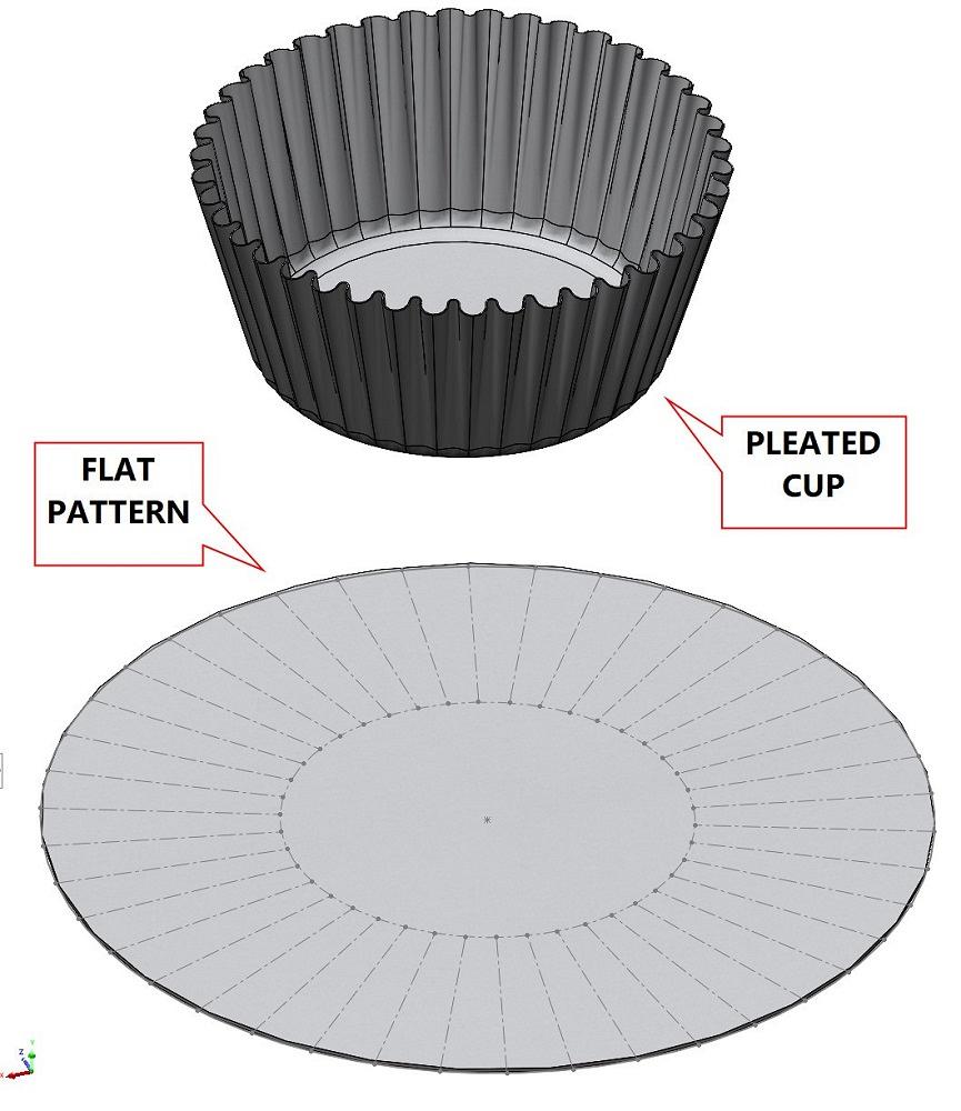
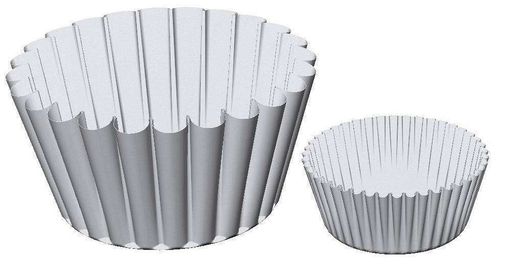
FIGURE 1. The flat pattern for a pleated cup is not magically unfolded. It was modeled with links between the flat and formed configurations.
Reader Joshua Raimond of Denver wrote to ask about a filter in CAD that was covered in a June 2016 column. The question: How is its flat layout modeled?
The item in question—a cupcake filter—is shown in Figure 1. There’s no magic here. The flat paper disk was created separately from the formed cup. The configurations determine which of two bodies to display—pleated or flat.
Short of an automatic flat-layout tool for pleated paper, there is nonetheless a CAD connection between the flat layout sketch and the formed cup. In this model, the size of the formed filter and flat layout are constrained parametrically.
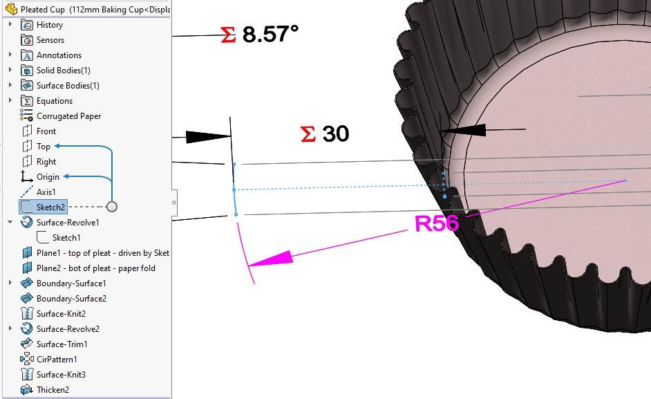
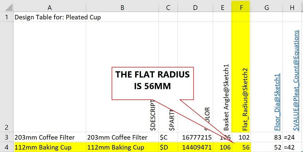
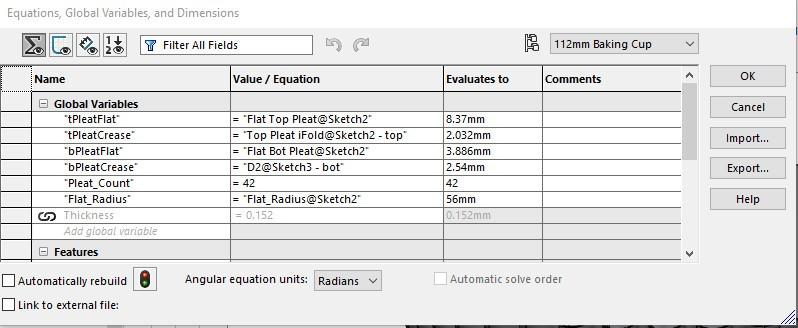
As a brief review of the cited article, Figure 2A shows the 3D filter with corresponding flat layout dimensions. The colors and symbols employed by the brand of mainstream 3D CAD being demonstrated indicate that the R 56-mm flat radius is controlled by a Design Table and the 30-mm wall length is controlled by an Equation. The Design Table that is doing the controlling is shown in Figure 2B, and the Equation Table is shown in Figure 2C. The intent of creating the global variables was to use them in subsequent sketches in the model. However, that is another story.
To review the CAD technique employed, configurations were created for both a big coffee filter and a smaller cupcake liner shown in Figure 3. Thus, both the Design Table and the Equation Table have entries for each configuration. (The original article goes into more detail regarding the surface modeling techniques used.)
Paper filters and flexible valves—what might such things have in common?
To paraphrase Abraham Maslow’s famous quote from 1966 about having a hammer and seeing every problem as a nail, let’s just say, “If the tool you have is a Design Table, it is tempting to treat everything as if it were Configured.”
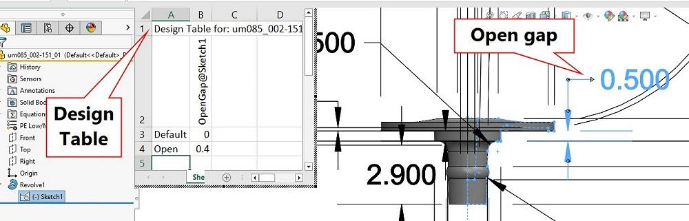
Recently, this CAD jockey needed a flexible valve. To model it, a revolved sketch is used. (This was done, of course, for minimum rebuild time.) The sketch for the valve is constrained so that the valve’s shape will adjust with the gap distance (between 0 mm and 0.4 mm in Figure 4).
Also shown in Figure 4 is a Design Table that sets up two configurations—default and open. In the open configuration, the gap is 0.4 mm; closed it is 0.0 mm.
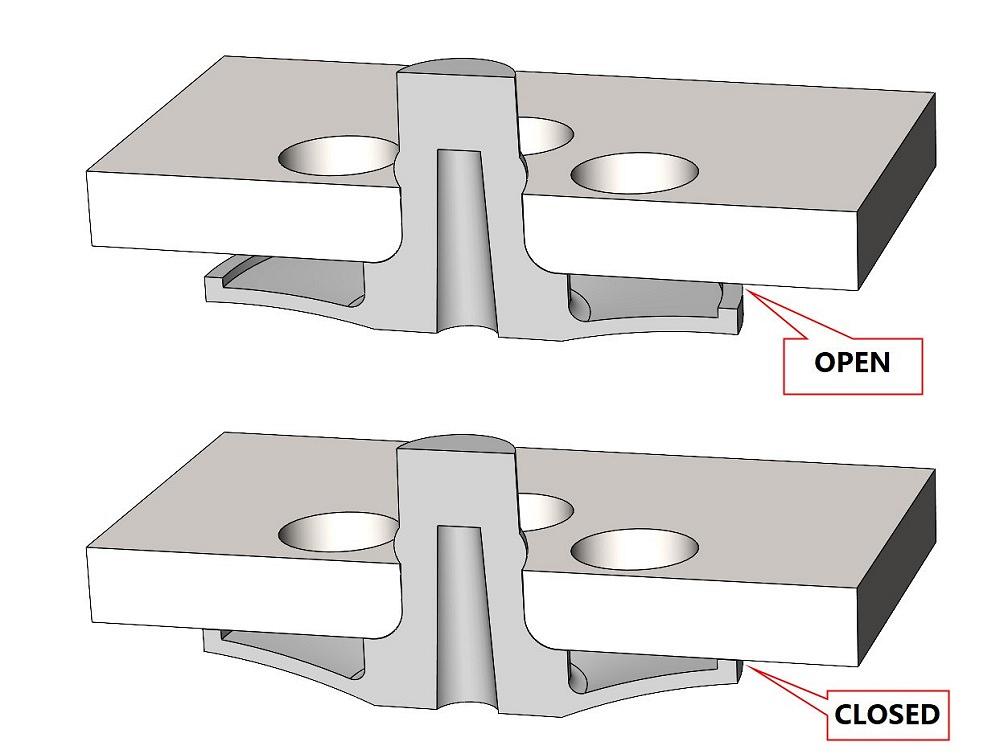
Figure 5 shows an assembly of the valve and a valve seat in cross-section. The assembly has configurations for open and closed. Those configurations select the valve’s open or default status, respectively.


The Fabricator is North America's leading magazine for the metal forming and fabricating industry. The magazine delivers the news, technical articles, and case histories that enable fabricators to do their jobs more efficiently. The Fabricator has served the industry since 1970.
start your free subscription
Easily access valuable industry resources now with full access to the digital edition of The Fabricator.

Easily access valuable industry resources now with full access to the digital edition of The Welder.

Easily access valuable industry resources now with full access to the digital edition of The Tube and Pipe Journal.

Easily access valuable industry resources now with full access to the digital edition of The Fabricator en Español.
In this episode of The Fabricator Podcast, Caleb Chamberlain, co-founder and CEO of OSH Cut, discusses his company’s...


