


Applications Manager
Laser welding isn’t new. The technology has proliferated for years in select industries like automotive, medical, defense, and aerospace. This includes OEMs and the suppliers that serve them. Even in this arena laser welding isn’t ubiquitous, but it isn’t rare either.
Still, venture outside these niches and into the general custom fabrication arena and you’ll find that laser welding remains a true rarity. Even if a fabricator does offer laser welding, it remains a fringe process, utilized for select jobs.
Arc welding remains the dominant way most fab shops join two pieces of metal together. Why, exactly? Volumes may have been a concern in the past, but today plenty of custom fabricators have adopted robotic arc welding with great success. The dominant concerns now involve part fit-up and fixturing, and the fact that many parts have designs that don’t account for laser welding requirements.
Those challenges are real, but overcoming them isn’t as difficult as you might think. This is thanks to not only the evolution of laser welding, but also the accuracy of upstream processes, including laser cutting and bending, as well as some fresh approaches to fixturing.
Laser welding calls for fabricators to think anew, not just about weld gap tolerances or fixturing requirements, but about the entire process of metal fabrication.
Fabricators are on a never-ending quest to get more out of what they have. To increase cutting and bending capacity, a fabricator can undertake process improvements, be it staging tools and materials or standardizing and documenting machine setup practices. But at some point, if a fabricator wants to increase cutting or bending capacity, it needs more equipment.
Thanks to fiber lasers for cutting and press brake automation for bending, each new machine is far more productive than the one that came before it. Depending on the material type and thickness it’s processing, a high-power fiber laser can have the cutting capacity of several CO2 lasers. A press brake with automated tool changes can be more productive than two or more conventional brakes. As fabrication technology progresses, each machine continues to produce more quality parts in less time.
Then comes welding and postweld grinding and finishing, processes that haven’t evolved in the same way. Sure, a shop can install robotic arc welding cells, even streamline programming with offline simulation, but for many products that slow, manual, arduous step of postweld grinding remains.
A programmer adding a little extra weld metal to a joint to account for gap variation can make the problem worse, as grind operators struggle to remove weld metal and polish the workpiece. Time spent grinding rises, as does consumable use. Excessive grinding isn’t a pleasant task, so worker turnover might increase as well, which comes with its own costs, including more training and the potential for more rework.
It’s little wonder fabricators have redesigned parts to eliminate welding, especially as press brake sophistication has increased. Instead of welding two or three parts together, why not form it as one piece? A complex bending setup with segmented tools might at one time have been impractically complex. But now, thanks to simulation software, tool-change automation, and intelligent angle correction, even an inexperienced operator can set up a complex job within minutes.
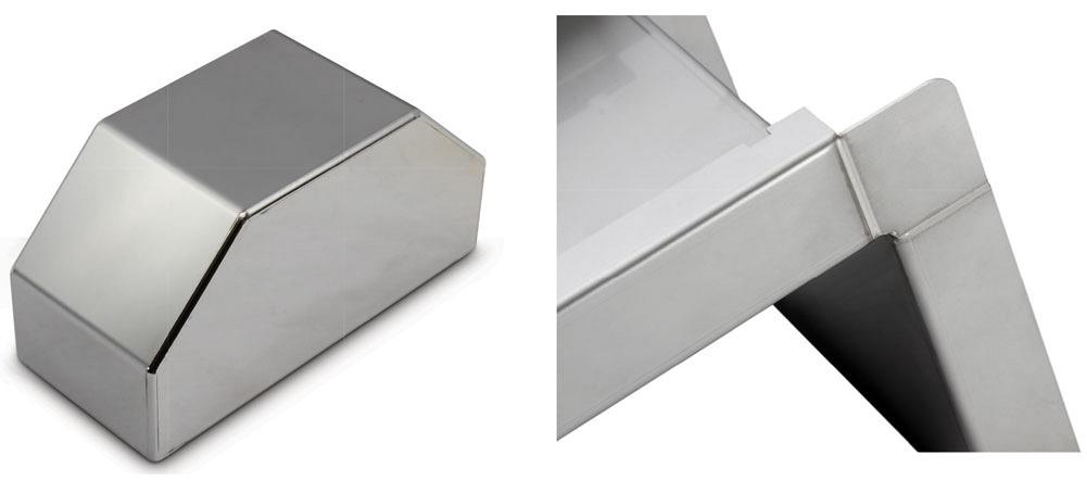
Figure 1
These as-welded stainless steel parts required no postweld grinding or polishing.
But this strategy might not work for every part, and it can make other operations more complex. Complex pieces might be difficult to stack and transport. Even if setup is easy, performing a complex bend sequence time after time can require significant concentration.
Like many aspects of fabrication, this situation has trade-offs. If a shop decides to cut and weld the pieces separately, it will have excess welding and grinding; if it combines the pieces into one complex part, it must deal with difficult bending operations.
But what if fabricators had another option? What if these pieces could be welded with a laser? A fiber laser can weld much faster than arc welding, of course, but speed of the weld itself is only half the picture. The other half, the elimination of grinding, can have an even greater impact on overall throughput.
Most custom fabricators are familiar with the fiber laser. The flexible glass fiber doped with ytterbium and pumped by diodes that output a specific wavelength—the essence of the technology inside the fiber laser power source—has had a dramatic effect on laser cutting capacity throughout the industry. In the years to come, the fiber laser could have a similar effect on welding.
The science of laser welding has come a long way. Like in cutting, welding with a laser comes down to analyzing how a certain material absorbs the laser’s energy. Fiber lasers for welding and cutting behave much the same as they travel from the power source and through the delivery fiber.
The difference happens at the processing head. Positioned millimeters above the material surface, the cutting head focuses the beam and the assist gas (the laser’s “cutting tool”) evacuates molten material to create kerf. A fiber laser welding head operates farther from the material surface and focuses the beam in such a way as to achieve the optimal weld. And like in arc welding, laser welding uses gas (such as argon) to shield the weld from the atmosphere.
In typical applications in custom fabrication, laser welding is autogenous; that is, it uses no filler metal. This reduces consumables costs and minimizes postweld finishing requirements (see Figure 1). Still, filler can be added if structural or cosmetic specifications require it. New wire feed mechanisms and liners now can feed some of the most challenging filler wires, including aluminum.
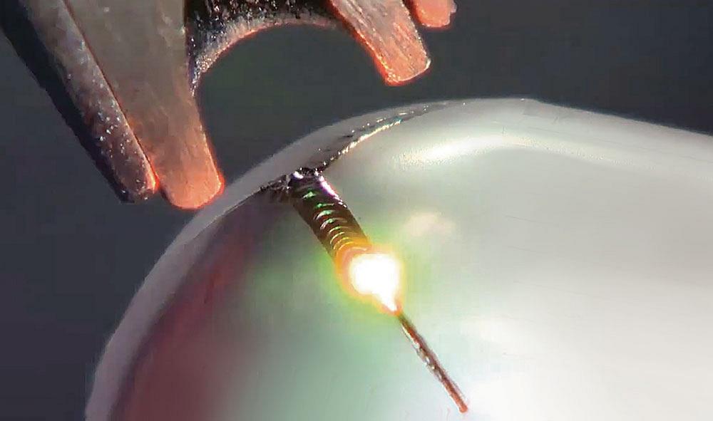
As with any welding process, establishing a good laser weld involves a lot of variables. A material’s weldability is a factor. Most common materials a fab shop will process—be it carbon steel, stainless, or aluminum—have been successfully laser welded for years, using both continuous wave and pulsed modes. Lasers have performed dissimilar-metal welding (see Figure 2), and specialized weld joint designs in galvanized material have even accounted for zinc outgassing. Moreover, a 1-micron multikilowatt fiber laser has been shown to successfully weld even the most challenging of materials, including copper (see Figure 3).
It’s all application-dependent, of course, and material challenges do arise. Overall, though, when it comes to laser welding, the limiting factor is not the material type, but material thickness. Ultrahigh-power fiber lasers have been shown to weld some extraordinarily thick material. In a typical fabrication environment, a 4-kW fiber laser can weld 0.25-in.-thick carbon steel quite readily.
Joint access factors into any automated welding situation, of course. Accessing tight areas can throw up a few roadblocks. But more often than not, small tweaks to a part design can alleviate the problem. This leaves two remaining, closely related challenges: fit-up and fixturing.

Figure 2
This laser weld joined copper to stainless.
Everyone knows that laser welding requires tight fit-up. Even so, the laser welding process itself has become more flexible thanks to technologies in the welding head. Specifically, the laser no longer must weld at a fixed point along a seam but instead can circle within a small area using a rotating lens (see Figure 4).
Also consider the accuracy of modern cutting and bending equipment. A lot of the discussion about designing parts for laser welding originated with sheet metal parts that happened to be stamped. Designing a part for laser welding often required making or modifying a stamping die—an expensive proposition.
But what if a shop has a modern fiber laser cutting machine and a press brake with precision-ground tooling? A design and fabrication process can be tweaked to ensure good fit-up for a variety of joint geometries without the need to machine an entirely new stamping die.
Moreover, such equipment is very repeatable. As long as operators choose the right press brake tools and call up the right program, sheets should form up the same way every time. If the tool change on the press brake is automatic, the possibility of incorrect brake tooling becomes even more remote.
Fixturing has been another hurdle, but it’s one that’s been lowered significantly in recent years. You could argue that high-speed fiber laser welding makes the fixturing approach even easier. True, when welding very thin stock—say, 0.020 in.—heat input has a noticeable effect on the joint location. In these cases, a laser welding setup can use similar heat-mitigation strategies as any arc welding cell, such as copper heat sinks and other backing material, or balancing clamping forces so the joint location doesn’t move during welding.
But for most workpieces, the laser welding process is so fast and has such a concentrated heat-affected zone (HAZ) that excess heat isn’t a factor; in fact, the nature of the HAZ makes the entire process more repeatable and precise. It also means that fixtures don’t need to compensate for that excess heat input, which in turn makes the simpler, less costly weld fixture easier to design and implement into production.
Today’s laser welding technology works with a range of fixturing strategies that, when married with precision upstream processes, can help optimize flow through the laser welding cell. The most basic is a location fixture (see Figure 5), which can entail off-the-shelf stops and toggle clamps, or it can simply be a few tack welds. Such a fixture can clamp an assembly to achieve proper joint fit-up, but the joint location might not be in the same place every time, and this is to be expected.
To adjust for this, a robot makes a dry run. With the laser off, the robot moves down the path of the joint, and the operator monitors a video screen that shows the joint as it passes under the welding head. If the operator sees the joint deviate from the program, he adjusts the robot path on-the-fly. With the dry run complete, the operator initiates the welding cycle.
This all may seem ridiculously inefficient for manufacturing, until you measure the actual throughput—and not just in welding, but in welding and postweld grinding and finishing. The robot welds so fast that, in some cases, making two passes (the dry run followed by the actual laser weld) may outpace traditional arc welding. But even if it doesn’t, overall throughput would likely still increase.
Thanks to concentrated heat input, a fast welding travel speed, and a minimal HAZ, most laser welded parts of a certain size are cool to the touch immediately after welding. These parts then can skip postweld grinding, one of the most time-consuming processes on the shop floor. If parts do undergo subsequent polishing, it’s usually to meet a certain cosmetic requirement.
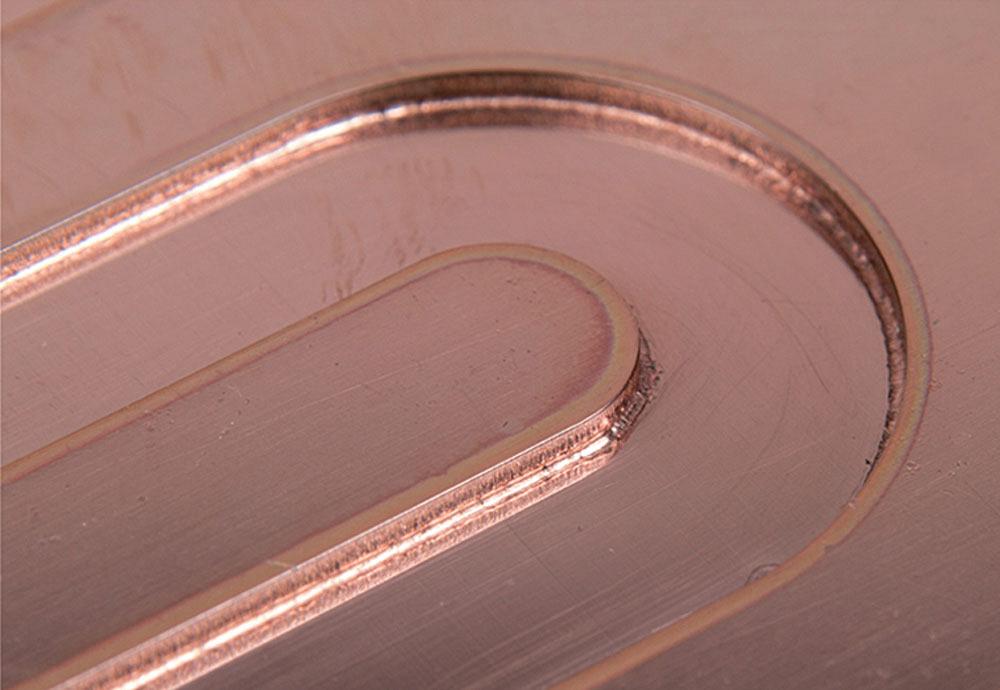
Figure 3
Multikilowatt fiber lasers have been shown to successfully weld challenging materials, including copper.
Using a location fixture and performing a dry run overcome a common conundrum in laser welding, and in all welding automation, for that matter: seam tracking. For years adaptive welding with seam tracking has made considerable advancements. The technology certainly has a place among various specialized welding applications, especially where it’s impractical to engineer out variabilities in upstream manufacturing processes. Otherwise, if upstream processes are precise and repeatable, a robot can weld perfectly well blind, without seam tracking.
Incorporating seam trackers fast enough to monitor fiber laser welds hasn’t been practical, either from a physical or economic standpoint. The dry run is a simple way to account for joint variability.
Ideally, upstream processes are repeatable and robust enough to eliminate that joint variability—but that’s only part of the fit-up equation. Another factor is part design. This can involve tab-and-slot and other self-fixturing techniques, as well as simple relief notches so that adjacent flanges can form up tightly.
And yet another factor is, of course, the fixture itself, which can push two workpieces together to ensure solid contact. Traditionally this has involved the production fixture, a cost that has discouraged many high-product-mix, low-volume fabricators from using welding automation. For high-volume applications, the production fixture makes sense. Designed right, the production fixture can present a joint to a robot so that it lays down a perfect laser weld time after time. The operator loads, clamps, unclamps, unloads, and reloads, with no dry runs required. Sophisticated fixtures can have components or even machined channels for hydraulic or air clamping, so operators can load and unload even faster.
But volumes don’t always justify such a hefty fixture investment, and here’s where another fixturing option plays a critical role: a prototype fixture built with interlocking sheet metal components, fit together using a tab-and-slot design and often simply tack-welded together. Sheet metal fixtures aren’t new, and precision laser cutting has made such fixture designs possible. Fabricators with robotic arc welding cells have used them for years. Also, “prototype fixture” is just a label. In fact, such fixtures have been used for repeat and high-volume work.
The laser forever changed the cutting department for custom fabricators, and it soon may do the same for the welding department. Imagine a situation in which an engineer imports a 3-D CAD file. It’s a rush job, but the weld joint attributes reflect what the company has laser welded previously. It’s a low-volume run of a few dozen assemblies that will be ordered repeatedly, not a one-off situation, so he decides that it’s worth doing more than resorting to a simple location fixture.
He builds a sheet metal fixture around an assembly. He also sees that, for joint access, he needs to put a relief in one area to ensure adjacent flanges mate tightly. He then notes that one area of the assembly could be self-fixtured with tabs and slots.
The job is then sent to the floor, with blanks and fixture components cut on the laser at the same time. Flat fixture components travel directly to welding, where they’re assembled and tacked together. A kit of parts is formed on a press brake with automatic tool change and then flows immediately to welding. At this point the fixture is staged, and the operator is ready to program the job. He then performs a dry run, welds the workpiece, and sends it to inspection.
The process is qualified and remaining workpieces are sent to the floor. Within hours, several dozen assemblies are welded, with no grinding required, and the job ships out the door.
So what happens to the fixture? That depends on the job, the fixture’s complexity, and available storage. Say a shop has rows and rows of prototype and production weld fixtures in inventory. If this most recent job isn’t likely to come up again for months, it may make more sense to scrap certain fixture components and perhaps keep the base plate and a few other components for use on future, perhaps very different jobs.
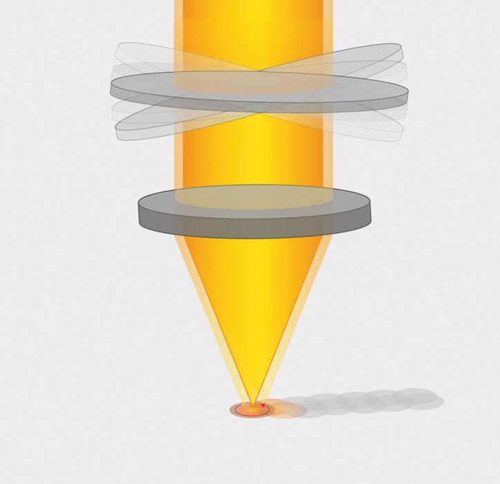
Figure 4
A rotating lens sends the beam in a circular pattern as it travels along the seam, allowing for greater fit-up tolerances.
The speed of fabrication—of designing and laser cutting weld fixture components, of bending, and of laser welding—gives the custom fabricator options. Should an assembly combine several sheet metal parts into one, albeit complex, formed part, perhaps with some mechanical fasteners? Or would it be faster or more consistent to keep forming simple and perform more laser welding—which, again, leaves a nice cosmetic appearance and usually requires no finishing? Forming may not be a problem if the shop has the latest equipment available, but what about those fastening requirements? How easy would it be to miss inserting a piece of hardware? Would it be easier to weld it and be done with it?
Such a discussion probably wouldn’t take place if arc welding and postweld grinding were the only option. Complex forming and hardware insertion can be tedious, but they’re faster than having to send parts to the grinding department. But put laser welding into the equation, and the discussion changes, giving fabricators more options to rev up part flow velocity on the floor.
Such velocity is now a reality in custom fabrication, and it’s more than just watching the eye-popping speed of a fiber laser make its way across a weld seam. It’s about looking at the big picture, forgetting what you’ve been taught, and thinking differently.
Dan Belz is FLW product manager and Abraham Andujo is applications manager at Amada America Inc., 180 Amada Court, Schaumburg, IL 60173, 877-262-3287, www.amada.com. Images courtesy of Amada America.
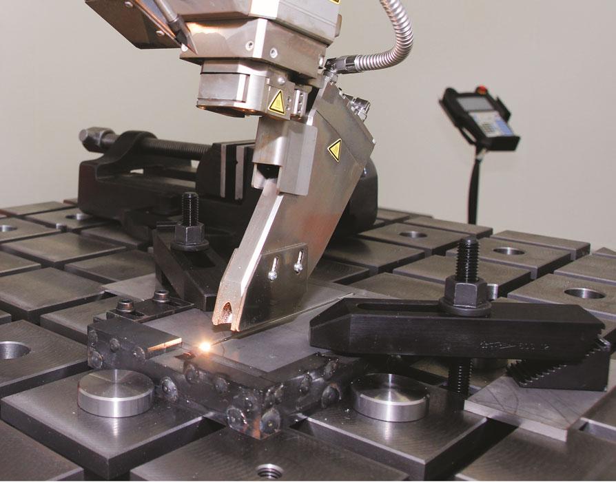
Figure 5
This location fixture was built quickly using off-the-shelf components.

The Fabricator is North America's leading magazine for the metal forming and fabricating industry. The magazine delivers the news, technical articles, and case histories that enable fabricators to do their jobs more efficiently. The Fabricator has served the industry since 1970.
start your free subscription
Easily access valuable industry resources now with full access to the digital edition of The Fabricator.

Easily access valuable industry resources now with full access to the digital edition of The Welder.

Easily access valuable industry resources now with full access to the digital edition of The Tube and Pipe Journal.

Easily access valuable industry resources now with full access to the digital edition of The Fabricator en Español.
In this episode of The Fabricator Podcast, Caleb Chamberlain, co-founder and CEO of OSH Cut, discusses his company’s...


