


Senior Editor
For most in metal fabrication, material remains the most significant item on the books. In the “2017 Financial Ratios & Operational Benchmarking Survey” from the Fabricators & Manufacturers Association Intl. (FMA), the average of direct material costs from respondents was 34 percent of sales. That’s more than all labor costs, both direct and indirect.
Some high-end fabricators—say, high-end weld shops serving the aerospace and defense sectors—may well have much higher direct labor costs. But by and large, paying for material involves the largest checks most fabricators regularly write. It’s no wonder they try to get the best deal they can.
But scrimping on material quality has its own costs, as any operator trying to cut or bend poor stock is painfully aware. And it stands to reason that a custom fabricator’s managers and purchasers should know good material and good coil processing and leveling equipment when they see it. This includes knowing some of the basic terms describing sheet flatness imperfections, and how service centers rectify those problems.
This has been Tom Hazen’s goal for years. President of Ellwood City, Pa.-based T.F. Hazen Consulting, his coil processing certification workshops at FMA have helped service center technicians better perform their jobs. But they have also helped purchasers and fabrication managers recognize best practices and, hence, identify good material and the good service centers it came from.
As one attendee told Hazen at an FMA seminar earlier last year, “This helps me know what I’m buying.”
The processes used to create sheet metal at the mill result in a sheet with trapped stresses. A mill rolling metal to create sheet performs a balancing act of tension and compression, a tug of war of forces pushing and pulling against each other.
A sheet becomes flat when those forces are at equilibrium. That is, the internal stresses in the sheet cancel each other out. The tug of war ends in a stalemate.
But as Hazen explained, those stresses are still there, tugging on the ropes; the tug of war ended in a stalemate, but the teams didn’t go home. So now, a laser cuts the material and essentially “snaps” some of the ropes holding those forces in equilibrium, causing workpieces to bow.
Herein lies the challenge with corrective leveling. Service centers uncoil the sheet (strip) and send it through levelers. The sheet remains flat—until the laser beam cuts it.
The trick is mitigating this as much as possible by spreading out and equalizing the stresses. For a rough analogy, think of this: Instead of just one large rope, the teams pull many different smaller ropes spread over a large area. Cutting a few of them doesn’t release a significant amount of stress, so the metal stays flat.
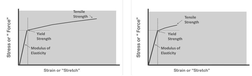
Figure 1
These basic representations of the stress-strain curve show the window of forming between the yield strength and tensile strength. As the yield gets closer to the tensile strength, as shown on the right, challenges in leveling (and any forming) arise.
The traditional and most common method is roller leveling, which sends material between a series of work rolls. Some alternative leveling technologies include stretch leveling, tension leveling, and temper mill technologies (four-high work rolls for shape control, etc.). Stretch leveling, as the name suggests, stretches the material in the longitudinal direction, working it through the entire material thickness by a sequence of clamping and pulling. Many in the industry tout its ability to produce extremely stable material. Tension leveling is similar, except that the operation is continuous, with material passing over bridle rollers that apply enough tension to elongate the material. These revived leveling technologies are used in conjunction with roller levelers. Regardless, Hazen cautioned that no one machine can correct for every flatness issue all the time.
Material that is not flat has unequal surface areas—that is, the top surface (on the outside of the coil) has more area than the bottom (inside) surface, or vice versa. This is what’s known as a surface-to-surface differential. A smaller bottom surface will force the top surface to curl downward or otherwise distort; a smaller top surface will cause the bottom surface to curl upward. The surface areas also can vary between the center and edge of the sheet width—what’s known as an edge-to-edge differential. This creates buckles and waves.
To correct these problems requires a delicate balancing act, because stretching the sheet in one area unavoidably affects other areas. “If I stretch the length, I change the width,” Hazen said, adding that this is due to Poisson’s ratio, or 0.33. “If I were to stretch a 100-square-inch sheet by 1 in., 0.33 in. would come out of the width.” And the opposite applies. In this sense, metal behaves just as a stick of chewing gum—stretch it, and the strip becomes narrower. A leveling machine operates under this reality, altering the material length and width in specific fashions to eliminate all the unlevel areas it can.
The stress-strain curve plays an integral role in all of this. In leveling, one yield-strain is the amount of elongation that occurs once the material reaches its yield point, the boundary between the elastic state (the material returns to its original shape after forming) and the plastic state (the material retains a new shape after forming). If one yield-strain for a sheet is 0.001 in., then when it reaches the yield point, the material moves by 0.001 in. per inch of length. If a material is tensioned to the point at which it elongates by 0.002 in. per inch of length, that’s two yield-strains.
“The number of yield-strains defines how much work you do to the material,” Hazen said, adding that leveling machine operators in the U.S. tend to use yield-strains to set their machines for a particular job—that is, they define how many yield-strains it will take to flatten the sheet and distribute and equalize its stresses.
One yield-strain is equal to the amount of springback a material has. If you work the material to one yield-strain, say 0.001 in. (again, just a hypothetical number), the material will spring back by the same amount. That’s because one yield-strain occurs at—but not beyond—the yield point. If you work the material to two yield-strains, or 0.002 in. in the current example, it will spring back by 0.001 in., or by one yield-strain.
Something called the Bauschinger effect also plays a role. This basically says that when something is tensioned and elongated, it yields more easily under compression. At the same time, the material will resist moving under tension as the tension rises, so the yield point rises and work hardening ensues. This relates directly to the slope of the stress-strain curve. If the material has a yield point of 30,000 PSI and the leveler is set to two yield-strains, the yield point may increase to 31,000 PSI. (Note that these numbers are purely hypothetical.)
The challenge arises when you have a narrow window between the yield point and ultimate tensile strength (breaking point), as you have for advanced high-strength steels. Work such material a little past the yield point (to, say, 1.5 yield-strains), and the yield point rises dramatically, leading to severe work hardening. As the yield point continues to rise, it gets closer and closer to the ultimate tensile strength (see Figure 1).
This leaves a narrow, or sometimes nonexistent, window for working the material before cracking occurs—hence the challenge of flattening such material or, for that matter, forming it in general. If leveling machines are rated to level a certain thickness range for conventional material, they almost certainly have a narrower range for high-strength materials.
Although plenty of alternative leveling processes are available, roller levelers remain the most common. Material is fed between sets of upper and lower rollers and emerges (ideally) in a flatter state.
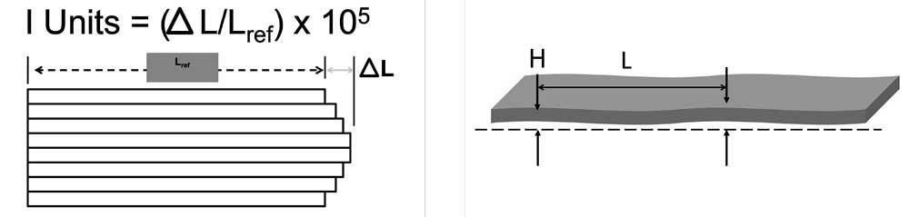
Figure 2
To measure a material’s flatness, cut the sheet into strips, straight across, and measure the distance between the shortest and longest piece. (The drawing exaggerates the difference in length to illustrate the concept.) Plug that difference into the formula shown, and you have the material’s I-unit measurement. You can also measure the height of the wave or buckle and the distances between them, then plug that difference into a formula.
How the roller works or bends the material hinges on its depth of penetration. This is defined as the difference between the material thickness and the roll gap, or the distance between the top and bottom rolls. If the roll gap is smaller than the material thickness, you have penetration, and the material is being worked. If the roll gap is the same as the material thickness, you have zero penetration. The roller leveler has rolls with the greatest penetration when the material enters and the least (or zero) penetration when the material exits.
The path the material takes between the entry and exit rolls is known as the differential path. The greater the roller penetration, the longer the differential path. A deeper penetration requires the material to travel a longer distance around the roll; but since the rigid bottom and top rolls force the material to run at the same speed (that is, the top and bottom roll hold the material and force it to move at the same rate), something has to give; this spurs the material to elongate.
More rolls also create a longer differential path, which is particularly beneficial for thin stock, Hazen said. Historically, some levelers have had as many as 23 rolls to correct errors in thin stock. Larger machines for thick material usually have fewer roll sets, like nine or 11. This is simply because thicker stock usually has fewer flatness issues to begin with, because the reduction (rolling) at the mill isn’t as extensive as it is with thin sheet.
When leveler operators know the material thickness, yield strength, and modulus of elasticity, they have the parameters to set the roll gap to attain the yield-strains to level the material. They plug those variables into an equation or the machine control or refer to a chart to determine the penetration settings for the rollers. In general, the more rolls you have in a machine, the more stable the material produced will be.
“But you don’t want the roll center distance too close,” Hazen added, “because then the gap setting becomes extremely sensitive. The rolls just touch the material, and everything changes.” As with everything else, the optimal roll distance depends on the material and application requirements.
A roller leveler’s roll diameter determines the gauge range the machine can handle. A machine with large rolls can handle thick stock but can have a hard time rolling thinner stock, simply because the roll diameters aren’t small enough to work (bend) the material effectively. As the material gets thinner, the rollers need to be smaller and smaller. Extremely thin stock may require alternative leveling methods, like tension leveling.
When ordering materials promised to be of a certain flatness, you need to know what you’re getting. Today many suppliers use a standard specified by ASTM called an I unit. An I unit quantifies how flat material really is, taking into account the height of the waves (or more broadly, the “nonflat conditions”) and the intervals between each peak.
Hazen added that this incorporates the difference in distance (in length and width) that must be overcome to flatten the material. To test for this, cut the sheet into horizontal strips. Lay these strips on a flat surface next to each other, then measure the difference between the longest and shortest piece. Plug these measurements into the following formula, where ΔL is the difference between the longest and shortest strip, and Lref is the length of the shortest strip: I units = ΔL/Lref × 105.
Another method is to use the special formula for buckles and waves: I unit = (H/L)2 × 246,760. This involves measuring the height of wave or buckle and the distance between waves or buckles (see Figure 2).
Leveling operators use I units to determine how much they need to work the material to make it flat. The way the math works, to correct for 1,000 I units requires a machine to be set to an elongation of 1 percent.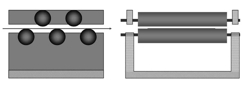
Figure 3
Non-backed-up roller flatteners have one set of rolls above and another set below the material. If the rolls are sized correctly for the application, these machines can remove coil set and crossbow.
Most roller levelers have backup rolls behind the main rolls. This gives the machines strength and allows for finer adjustments. But non-backed-up roller flatteners, those with one set of rollers on the top and bottom, are still in use (see Figure 3). These basic machines often have rolls that aren’t highly powered, and often they can’t work material beyond a couple of yield-strains. Since the rolls are not supported, they deflect and can cause edge wave.
If sized correctly, with rolls large enough to handle the sheet thickness and yield-strength range you need, these machines can remove coil set, or longbow, which occurs naturally any time sheet is wound into a coil (see Figure 4). Coil set is what’s known as a surface-to-surface length differential. The act of coiling causes the top surface to stretch slightly, making the top surface of the strip longer than the bottom. When uncoiled, the strip tends to curl down, wanting to keep its coiled shape.
“Almost every coil has [positive] coil set,” Hazen said, adding that an exception would be certain high-strength materials (which also need more than a non-backed-up roller flattener). “Their yield strength is so high that in the act of coiling it, you never bend it to a radius that would put the coil set into it.”
Most roller levelers are designed to correct positive coil set, where the coil curls down. In these machines, the last roller on the bottom turns the material up as the material exits. But to handle reverse coil set, where the coil curls upward, the final exit roll needs to be on top to turn the material down as it exits the machine. Some systems have an extra top roll that can be used just for this purpose.
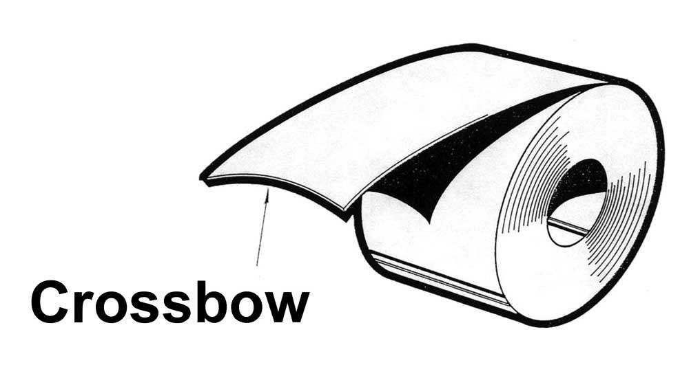
Non-backed-up roller flatteners also may be able to correct for crossbow, which is nothing more than coil set across the width of the strip, otherwise known as a surface-to-surface width differential. In this case, the top surface of the sheet is wider than the bottom surface, so the sheet edges curl downward (see Figure 5).
Note that coil set and crossbow are closely related. “One creates the other,” Hazen said. With coil set, the bottom or inside surface of the material (meaning the surface closer to the center of the coil) is shorter than the top or outside surface; that is, lengthwise, the strip has more surface area on the top surface than on the bottom surface.
“So in this case, you want to make the inside surface longer by stretching it,” he said. “But you don’t get something for nothing. That material you’re using to make it longer is coming from the width and the thickness.” Stretching the material on the inside surface can take material away from the inside surface’s width. This in turn makes the inside surface width shorter than the outside surface, which produces crossbow.
“So if I want to take out coil set, I want the machine to not only lengthen the inside surface, but also shorten the outside surface width. And this is what a roller leveler does. It’s compressing and stretching. If I stretch, I make something longer, and if I compress, I make it shorter.”
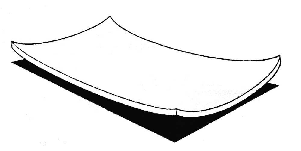
The combination of coil set and crossbow causes unique shape defects. One is called a dished defect (see Figure 6), which is essentially coil set and crossbow occurring in the same direction: positive (curling downward) or negative (curling up). How does this happen? The inside (or bottom) surface is smaller than the outside surface (top). Correcting for this requires a multipronged approach. Just pushing down on the center won’t do; as the edges try to flatten, center buckle arises in the center. To correct this fully, you need to make the top surface longer (correcting coil set) and wider (correcting crossbow).
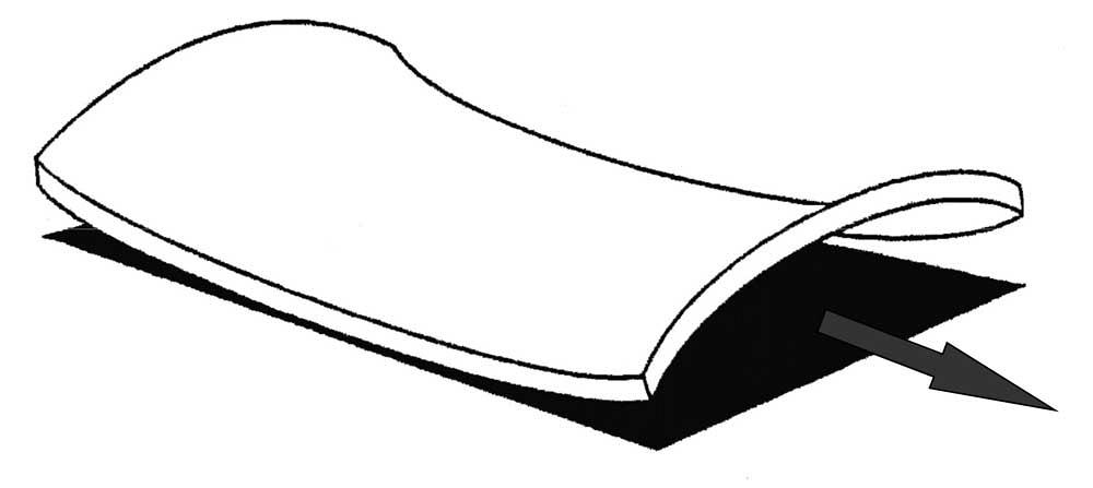
Then comes saddle (see Figure 7), which is coil set and crossbow occurring in opposite directions: positive (curling downward) and negative (reverse, curling up). To eliminate the saddle defect requires corrections for both crossbow and coil set. If just one is corrected for, then other flatness defects such as edge wave (described later) can emerge.
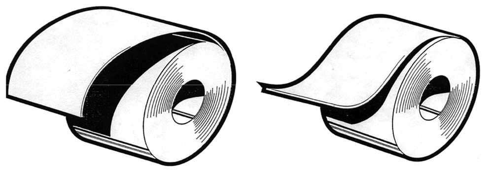
Figure 4
Coil set (left) occurs when the sheet curls downward as it’s uncoiled, wanting to keep the coiled shape. Reverse coil set (right) occurs when the material flips upward.
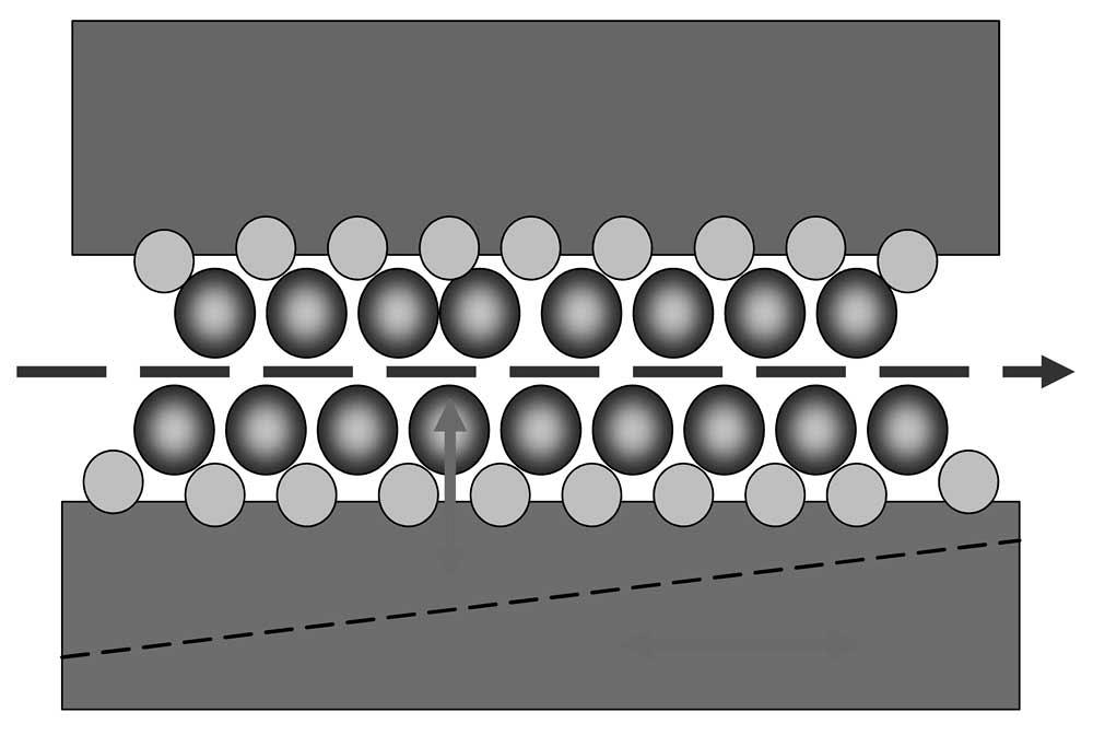
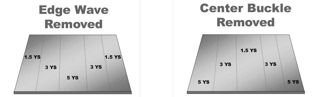
If a machine can change the work roll configuration (using the machine’s backup rolls behind the main rolls) so that each backup roll bank across the material can be adjusted to penetrate the sheet a different amount, this changes the penetration (or bending amount) across the width. In doing so, the system applies different yield-strains across the material (see Figures 8 and 9). This is known as precision corrective leveling.
These levelers work out imperfections in an optimal way, especially for a defect category called edge-to-edge length differentials. This occurs when the length of material differs across the width of the material—that is, from one edge to the other.
This includes edge wave and center buckle. With edge wave, the outside edges of the strip are longer than the middle of the strip. That extra material manifests itself in waves along the edges. With center buckle, the opposite is true. The center of the strip is longer than the edges, and, again, that extra material manifests itself in waves down the center of the sheet.
The precision corrective leveler can work (penetrate) the material more in the center and less on the edges to work out the edge wave. To remove center buckle, the opposite occurs: The center rolls penetrate less while the edge rolls penetrate more. This works the edges more; once their length equals the length of material down the center of the sheet, the center buckle disappears.
All this merely scratches the surface (in the metaphorical sense) of leveling. As Hazen described, the truth is that much of the expertise in leveling comes from experience, including trial and error. Scientific studies do exist, of course, “but if you ask anyone in this business, they’ll say that, on a deep level, we don’t know why certain materials level the way they do.”
All the same, many leveling practices are founded on good science and good reasoning—about inducing certain yield-strains in certain areas in certain ways. It’s not all black magic.
When Hazen visits a service center or any other operation that’s leveling material, he talks with the operator and picks his brain. “Sometimes I talk to them about how they do their jobs, and they tell me, ‘Well, I just put on more pressure.’ They really have no idea about the intricacies of what they’re doing. The pressure isn’t what’s making the leveling happen. The pressure allows the rolls to bend the material, and it’s the bending that’s creating the elongation. But once you explain it to them, then they get a better concept of what [they’re] trying to do.”
From a fabricator’s perspective, it boils down to knowing what good leveling practice looks like and asking good questions. As for that fabricator’s purchaser who attended Hazen’s workshop hosted by FMA, he now knows what’s going on at his service center’s leveling operation. Most important, he has some good questions to ask.
Images courtesy of T.F. Hazen Consulting, 724-752-8954.
For more on FMA’s coil processing resources, visit www.fmanet.org.


The Fabricator is North America's leading magazine for the metal forming and fabricating industry. The magazine delivers the news, technical articles, and case histories that enable fabricators to do their jobs more efficiently. The Fabricator has served the industry since 1970.
start your free subscription
Easily access valuable industry resources now with full access to the digital edition of The Fabricator.

Easily access valuable industry resources now with full access to the digital edition of The Welder.

Easily access valuable industry resources now with full access to the digital edition of The Tube and Pipe Journal.

Easily access valuable industry resources now with full access to the digital edition of The Fabricator en Español.
In this episode of The Fabricator Podcast, Caleb Chamberlain, co-founder and CEO of OSH Cut, discusses his company’s...


