


Is roll forming an option?
The basics behind justifying one of the oldest and still misunderstood metal forming processes
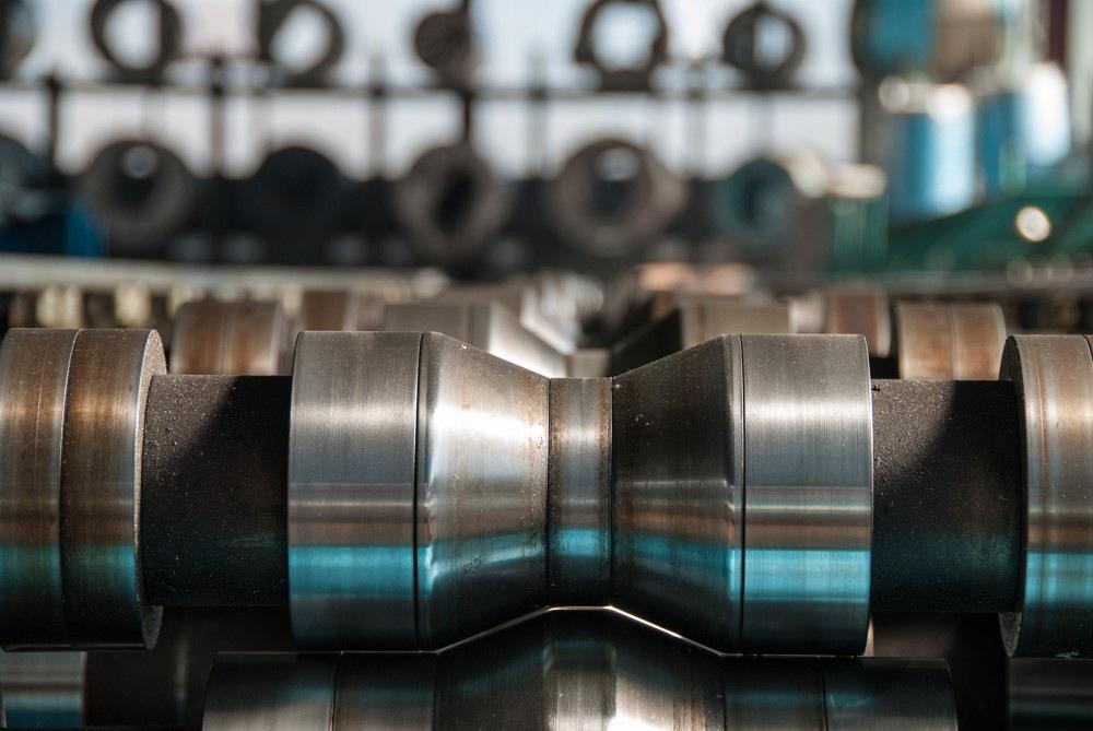
Roll forming is one of the oldest and yet still misunderstood metal forming processes. And its capabilities continue to grow. Getty Images
The following article is based in part on “Justification for roll forming,” prepared for the FABTECH conference by Brian Rodgers, senior application engineer, Formtek Inc.
The fundamental concepts behind roll forming go back to Leonardo da Vinci. The first continuous roll forming lines can be traced back to the 1910s. Yet even after all this time, many still don’t know what roll forming really is. It’s a staple in certain sectors like automotive, aerospace, and the metal building industries, but to many the century-old metal forming technology remains entirely novel.
Knowing just what roll forming can and cannot do opens the door to a host of metal forming possibilities. And in most cases, it all starts with a continuous part profile with high-volume requirements.
Roll Forming 101
Even those who do know roll forming continue to be amazed about what’s possible. These days some manufacturers have developed proprietary methods to push roll forming’s limits, coining the metal to produce a part profile that looks extruded, not formed from a coil of sheet metal. Others have found ways to form shapes with noncontinuous cross sections, like a C-channel that “squeezes in” like a bowtie.
But most conventional roll forming applications still require a continuous cross section, or profile. It could be a simple C- or U-channel or an incredibly complex, irregular shape. The part can be straight, curved, even twisted into a helix. But amid all this geometric variety, the part profile is continuous.
To understand why requires a basic understanding of the roll forming method (see Figures 1 and 2). Material emerges from a coil or blank through a precision leveler (if the application requires it), and then into the first stand of a roll forming line. The upper and lower roll tools on every stand perform a certain amount of forming that together create what’s known as the roll form flower, an illustration showing how a part is rolled to its finished profile.
As the metal strip feeds through, the upper and lower roll tools on each stand form the profile a specified amount that depends on the metal thickness, grade, material yield and tensile strength, part geometry, feed rate, and other variables. And just like stamping and press brake forming, roll forming must deal with springback. The metal forms as it squeezes through the first set of rolls, then relaxes slightly (thanks to springback) before entering the next roll set or forming pass. That next station forms the piece to the next “petal” of the flower pattern, accounting for previous springback from the prior pass. And so the process continues until it reaches a straightening station, or sweep block, which eliminates or induces camber (see Figure 3), before being completed or cut to length at the end of the line. The resulting parts can be straight, curved, or even formed into a helix pattern.
Roll Forming Dies
Roll forming lines incorporate a variety of rolls, of course, but they also have at least one but often several kinds of dies. Every continuous line has a cutoff die that cuts the final roll formed piece to length (see Figure 4). Some blank-fed roll forming lines are hand-fed, but others have a pre-blank die that cuts the strip to length before being fed into the roll forming line.
Other dies on the line punch holes and other cutouts. When it occurs before the metal is formed, it’s called prenotching or prepiercing. When the press operation occurs after or between forming stations, it’s called midnotching—a sometimes necessary step if, say, punching a hole before forming would lead to undesirable stretching.
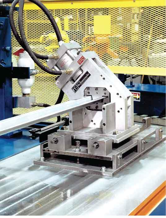
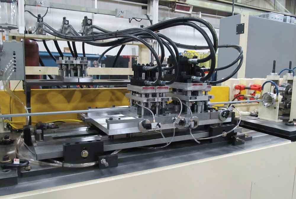
Notching and blanking dies can remain stationary, fixed to a ram and bolster, or they can ride along tracks mounted to the bases, where the entire hydraulic or pneumatic press assembly, or sometimes just the die, moves linearly (see Figure 5). These flying dies increase a roll forming line’s flexibility.
Some lines incorporate specialty dies that form embossments, slots, tabs, louvers, and other value-added features. On applications that require high rates of speed, a rotary die can be used. As the die rotates, the cutouts and forms are created at speeds over 100 feet per minute.
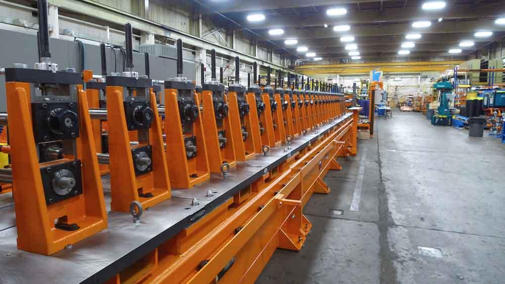
This rafted roll former is designed to streamline the changeover process. Image provided
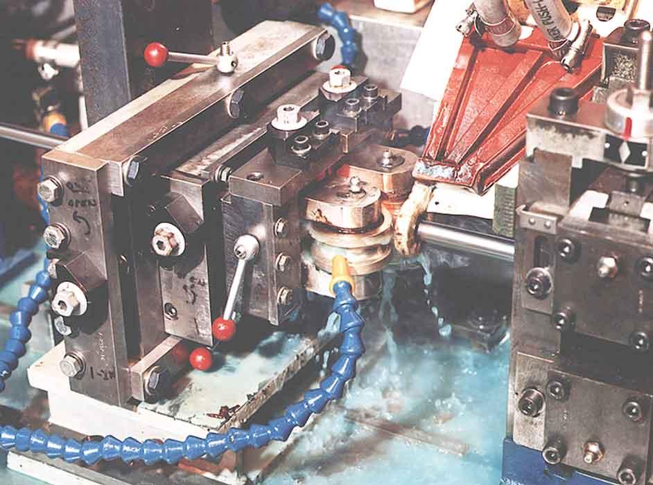
If you see a roll formed part with spot welds along a seam—and no secondary spot welding station on the floor—it’s highly likely they were put there with a process called rotary resistance spot welding, which traps the material between two copper electrode wheels and allows welding to take place while the material is moving. This process is used in the automotive industry for bumper beams and door frame sections. In fact, for many years rotary spot welding was the preferred choice for bumper beams. Today many roll form lines produce custom welded tubes with high-frequency welders (see Figure 6).
Roll Forming Idiosyncrasies
Like any forming process, roll forming induces stresses into the part, which can result in some kind of distortion. This includes what’s known as end flare. If not compensated for, all roll formed parts will emerge with a toe-in on the leading edge of the part and flare on the trailing edge. The phenomena usually occur within the first and last 6 in. of the part length. The root causes have to do with the metal’s elastic properties, similar to springback in stamping and press brake forming.
To compensate for this, roll form lines have antiflare units comprising a series of blocks, rollers, and mandrels. The units overbend portions of the part so that it springs back to the desired shape.
One of roll forming’s greatest strengths is its ability to form a variety of material, including high-strength/low-alloy (HSLA) steel. Engineers can accommodate for bending stresses by controlling the roll pressure with inboard and outboard adjustments on the roll stand. They can also reduce the number of degrees bent at each roll stand. For instance, instead of bending the part 25 degrees in one tool stand, an engineer might decide to break that form into 5-degree increments among five roll stands.
Additional roll passes can help work the “material memory” out, but those passes need to be strategically placed. A part’s geometry sometimes requires certain roll stands to work the material more than others. Adding stands can make a world of sense, but they need to be placed where they’ll do the most good, and this can vary with the application.
Regardless, adjusting the number of stands (and the tooling on each) gives engineers another “knob to turn” to tune in and perfect the process. All those “tunable knobs” is one reason roll forming can form so many different kinds of materials into such a wide variety of shapes.
Width and Length Factors
Sometimes roll forming makes helixes and other shapes impossible to make any other way. But when the decision to roll form is based on part geometry alone, it usually has to do with the part’s size.
Theoretically speaking, roll forming has no limit on part length. The only true limits are practical: that is, how you handle the part as it emerges from the line. Extremely small, short parts are sometimes handled with chutes. Slug evacuation systems under dies can actually turn into part evacuation systems; that is, the slug is the part.
At the other extreme, parts can be extraordinarily long. Stamping presses have bed size limits, and press brake beds can be only so long. But even the most compact roll forming line has no theoretical limit on part length. The only limiting factor is having the space and capability to manipulate the formed part.
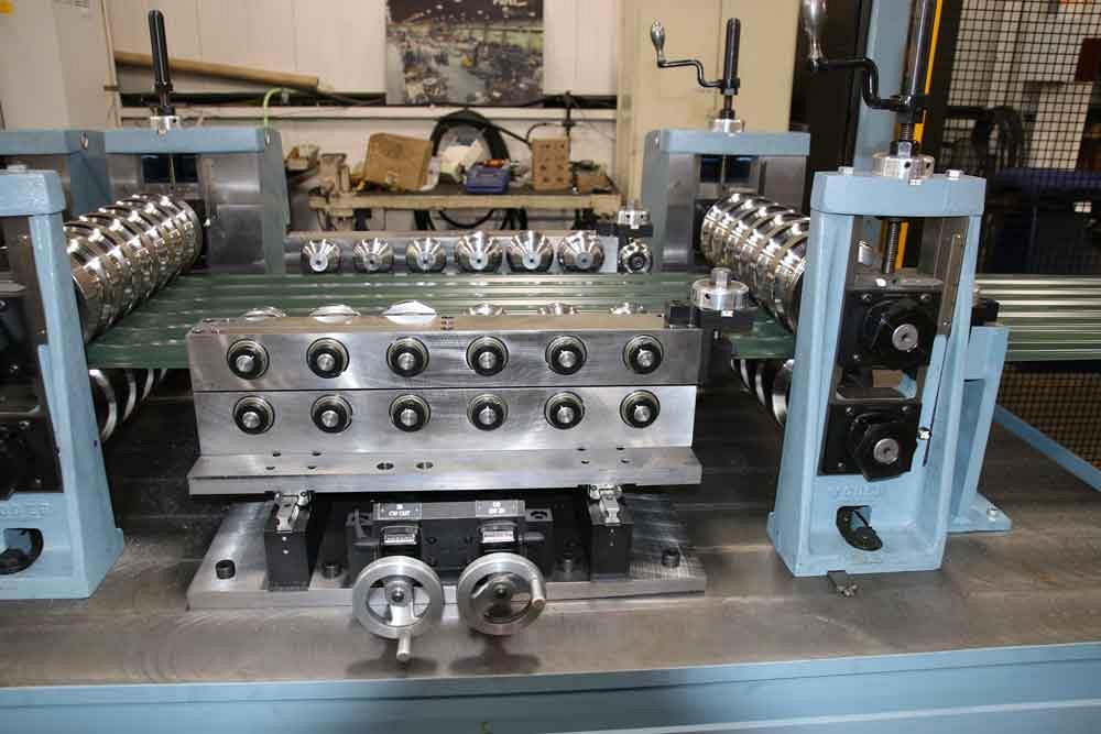
Regarding width, the only limiting factor is usually the width of a coil. Some roll form lines have been known to process a wide range of workpiece widths (see Figure 7). These include duplex lines that form only near the material’s edges and can move in and out to accommodate different widths without tool changes.
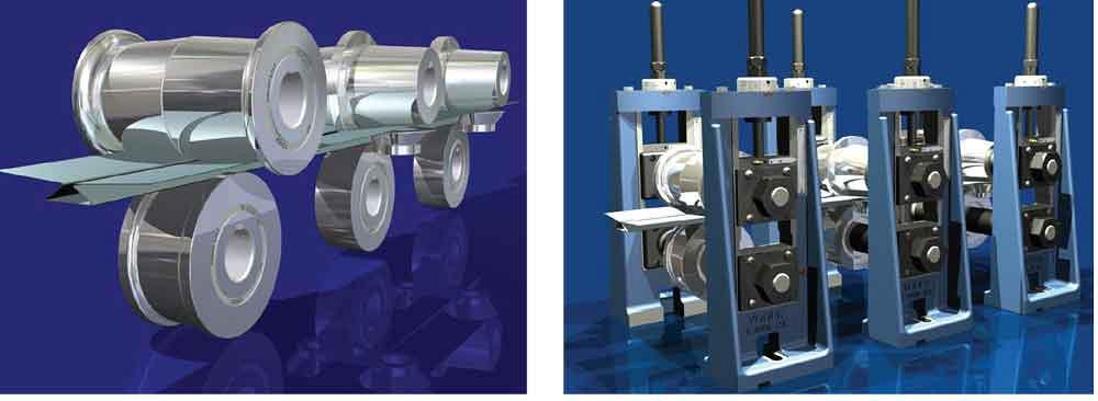
Figure 1
A roll form profile is formed through sets of roll tooling. Roll stands are removed to illustrate the workpiece transition.
Changeover Considerations
Duplex lines that reorient themselves quickly illustrate how flexible some roll forming lines really are, particularly when processing part families that share certain attributes. Some roll form lines in the bleacher and seating industry can produce one different part after another. The parts share the same profile but have different lengths and hole patterns. It’s all kitted and shipped in the exact order installers need them on the job site.
Quick changeover in roll forming can occur in various ways. For instance, a specialty line can be built to roll form a handful of different parts, each of which uses specific roll stands. This works only for certain kinds of part geometries and certain tolerance requirements—essentially, the roll form line is custom-built around the needs of a specific, usually high-volume part mix—but it is an option in select circumstances.
New programmable controllers can change punch patterns, part lengths, and other attributes. The changeover might not be immediate or on-the-fly for different patterns per part, but it can happen in a matter of minutes.
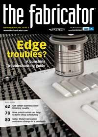
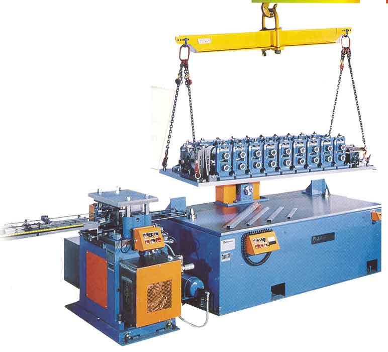
Another quick-change option is to use rafted lines (see Figure 8), where entire groups of upper tools are preset in a raft and can be lifted into place. Small roll forming lines can consist entirely of a single raft that can be swapped out as needed. This technology introduces quick changeover for broader product mixes. Rafted changeovers aren’t immediate, but they’re faster than the traditional manual changeover, in which operators can spend hours manually swapping and aligning tools.
Labor Factors
Labor costs in roll forming typically run between 3% and 15% of the total job cost. Why the wide range? It’s thanks largely to the varying levels of automation available as well as the product mix and complexity of the roll former line.
A roll form line requiring manual changeovers can have high labor content, depending on the number of changeovers the line requires. At the other end of the spectrum, some companies might have just one employee managing three separate lines. Controllers manage most of the changeovers, and parts are offloaded automatically into kanban bins. That one employee might spend most of his time monitoring the process and staging new coils for the next job. In some high-production environments, a roll former might have no operator at all.
Reducing labor content even further, automated calibration helps reduce some of the black magic of roll setup and in many cases can actually make real-time adjustments. Just as press brakes offer real-time angle measurement, roll forming lines now offer real-time adjustments to account for material variability and keep the final part geometry well within the tolerance window.
After setup, roll forming has always offered high consistency from part to part. Standard profile tolerances are ±0.030 in., with ±2 degrees on the angles. Twist tolerances can be less than 0.120 in. over 40 in.; camber tolerances can be within 0.040 in. over 40 in.; and bow tolerances can be within 0.040 in. over 40 in.—though again, these numbers vary depending on the application. All these tolerances can be even tighter depending on the part geometry. Regardless, automated calibration just takes that consistency to the next level.
All this said, labor content in roll forming is just one piece of the puzzle. A roll form line even with high labor content still could help reduce overall costs, especially if the line integrates secondary processes like welding. For instance, a large roll form line might require one operator to monitor the roll form process and another to run and monitor the welding operation. Labor content at the roll former might rise to 15%, but because multiple secondary operations are eliminated, overall costs plummet.
In fact, eliminating secondary processes is one big reason many parts that were previously extruded become roll formed. Extruding has the benefit of simple, inexpensive tooling that can produce extremely complex geometries; and because you’re not starting with sheet metal, you don’t have to worry about end flare and other metal forming idiosyncrasies.
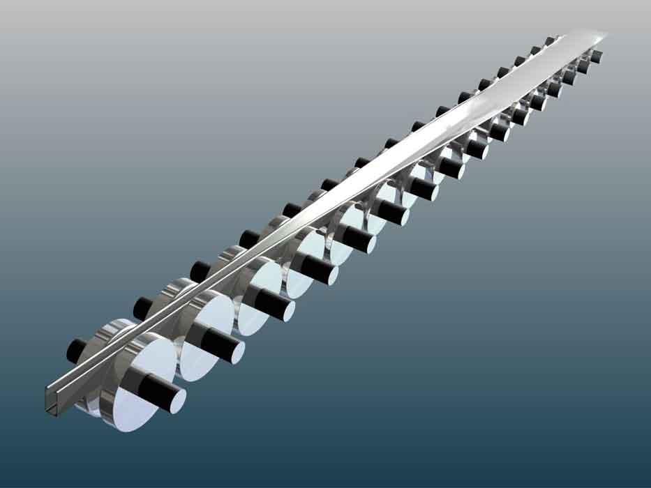
Figure 2
A solid model, with the upper rolls removed for illustrative purposes, shows how a metal strip forms as it passes through different stations in a roll former.
Because we live in a global market, reducing labor costs is key. Numbers can vary depending on the application, part geometry, and market demand, but in a typical scenario, roll forming becomes competitive when the material content makes up between 60% and 90% of the total job cost.
Volume and Capacity
Many parts start their life cycle on a press brake but then end up being produced on a roll former. In fact, once part volume exceeds 250,000 linear feet a year (note this is feet, not number of parts), roll forming often becomes the most cost-effective option.
This number varies with part complexity, though. A part with just a few simple bends might require up to 500,000 linear ft. a year for roll forming to make sense. Then again, you could have only 10,000 linear ft. a year, but because the part is so complex, roll forming is still the least expensive option. The numbers could go even lower if a roll former helps eliminate secondary welding or other operations.
Know that these numbers are just generalizations. Consider a part that starts at a manual press brake, then is transferred to a robotic press brake cell. The robot cell can meet customer demand, but the part itself might not be taking advantage of the bending cell’s strengths. Offline simulation, intelligent material staging, flexible grippers, and automated tool changing all create a system that can produce an extraordinarily wide variety of parts—and it’s not limited to parts with a continuous profile.
And yet the robotic brake cell continues to produce large volumes of a narrow part family, all of which have a part profile perfectly suited for a coil-fed roll forming line. Why not move the part family to a roll forming line, then open capacity at the robotic bending cell to form other relatively low-volume parts?The decision to roll form—or use any other process, for that matter—really boils down to making the best use of metal forming capacity. Sometimes this calls for questioning the status quo. Considering the state of the world, all the future uncertainty, and the continual advancements in manufacturing technology, questioning the status quo has become more important than ever.
About the Author
About the Publication
subscribe now

The Fabricator is North America's leading magazine for the metal forming and fabricating industry. The magazine delivers the news, technical articles, and case histories that enable fabricators to do their jobs more efficiently. The Fabricator has served the industry since 1970.
start your free subscription- Stay connected from anywhere

Easily access valuable industry resources now with full access to the digital edition of The Fabricator.

Easily access valuable industry resources now with full access to the digital edition of The Welder.

Easily access valuable industry resources now with full access to the digital edition of The Tube and Pipe Journal.

Easily access valuable industry resources now with full access to the digital edition of The Fabricator en Español.
- Podcasting

In this episode of The Fabricator Podcast, Caleb Chamberlain, co-founder and CEO of OSH Cut, discusses his company’s...
- Trending Articles
1
Tips for creating sheet metal tubes with perforations

2
JM Steel triples capacity for solar energy projects at Pennsylvania facility

3
Are two heads better than one in fiber laser cutting?

4
Supporting the metal fabricating industry through FMA

5
Omco Solar opens second Alabama manufacturing facility
