


Contributing Writer
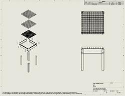
Figure 1: The title block of this drawing is displaying the values of custom properties. In this example, the data entry for those values is in need of correction.
This month we continue with the cutting table project. Last month we left off with the drawing shown in Figure 1.
Right now this drawing has some problems:
Before we look at different ways to correct this problem, here’s a quick reminder: Some of the verbiage used in the discussion of CAD modeling in this column is unique to the software I’m using. However, you will find that other software offers similar functionality in most instances, even if wording and commands are different than those mentioned here.
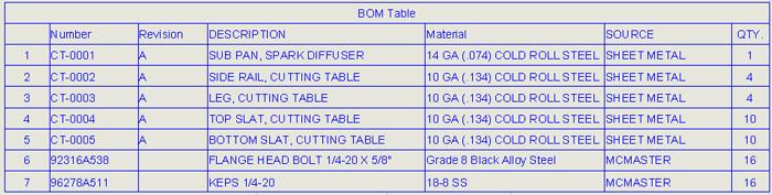
A BOM (see Figure 2) is just a table intended to help with purchasing and assembly. For background, let’s consider three general methods of creating any table on a drawing—manually draw it, use spreadsheet software, or use tools built into the CAD software.
Manually drawing a table by sketching rectangles and lines and then typing blocks of text is indeed one way to create a table on a drawing, but it is labor-intensive and not very easy to edit. This is a technique I used decades ago. I’m pleased to report that better methods are available today.
The Windows® operating system provides methods for embedding one document inside of another; for example, dragging a picture into a text document. It is not difficult to create a spreadsheet and then to drag it into a CAD drawing. It is slightly more difficult to get that spreadsheet to populate automatically with information found in the CAD model. I seldom drag spreadsheets into drawings to create tables, but it can be done.
The software I use provides tools for using either type of table, Excel® spreadsheets or SolidWorks® “native” BOM tables. To a great extent, these Excel-based tables are linked directly to the CAD model, but I find it easier to just use the native SolidWorks tables in drawings. That’s the method I’m going to discuss in this article. By the way, the BOM table in the drawing can be exported to create a stand-alone spreadsheet if needed.
A BOM generally has a specific function—to describe in detail all of the components required to manufacture an assembly. The amount of detail in the table is a matter of preference. The default BOM template that ships with SolidWorks has a minimalist approach. It is not unusual to need to customize that template to make it work for you. Later we’ll examine how to customize the template to make the routine production of assembly drawings less labor-intensive. But before that, it is important to understand where the information displayed in the BOM is coming from.
Windows provides methods for application software (like 3-D CAD) to embed custom properties in the documents the application creates. You can use Windows Explorer to see the custom properties for any file (see Figure 3). Custom Properties are simply storage containers for data. You have complete control over the name you give a custom property and the data that is stored and retrieved using that name. You might create a custom property named Revision with a value of A. In Figure 1, a custom property exactly like that is being used to fill in the revision shown in the title block at the lower right.
Keep in mind that any Windows document can have custom properties. In the specific example of SolidWorks software, the drawing files, part files, and assembly files are likely to have custom properties. What makes this potentially confusing is that all of those documents could contain custom properties with identical names. For example, Revision might appear in a part, an assembly, and in a drawing file.
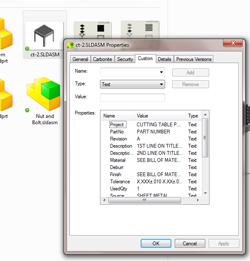
Figure 3: Custom properties can be displayed for any file using Windows Explorer.
Just because custom properties have the same property name does not make them the same property value. The Revision property in the drawing is completely separate and unique from the Revision property in the assembly file. Those Revision properties will have their own values. For instance, the drawing could have a custom property named Revision with a value of A, and the assembly could have a custom property named Revision with a value of B.
A BOM might use properties like Vendor, Vendor PN, Material, and Description. Should those custom properties be saved in the drawing files or in the component files? That is a matter of personal preference, but I recommend keeping as much procurement and manufacturing information as practical embedded at the component level. Use the drawing and BOM templates to create documents that display the embedded information in a logical organization. If you’re creating a drawing, then some of the embedded information from the models shown in that drawing would appear in the drawing’s title blocks and tables.
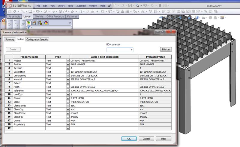
Figure 4 is a screen shot of the custom properties list for our cutting table in Figure 1. The values still need correcting, but you can see from the list of names what sorts of information is commonly saved in the assembly.
We could embed all of the data into the drawing file. To fill in the title block on our drawing, we’d just type the values right onto the drawing sheet; no custom properties are needed. If we did want to use custom properties, we could put all of them into the drawing file.
The problem with keeping all of the data in the drawing is twofold. First, it is tedious, and it requires diligence to locate the entered data in the right spot on the drawing every time. Second, if the part or assembly shows up in another project on another drawing, the data entry has to be completely repeated each time. This approach—putting all of the data entry into the drawing file—makes drawing production very dependent upon human perfection.
To contribute to a less demanding work flow, we’re going to set up a drawing template. All drawings that we create using that template will display the values of custom properties in the correct locations on the drawing every time. It won’t matter if we’re making a drawing for a part or for an assembly. All that matters is that the part or assembly must have custom properties with the right names to match the setup of our drawing template.
Additionally, the data entry for the values of those named properties must be completed before any meaningful data will appear. At this point we need a template for the BOM tables and another template for drawings.
To display the part number in the title block, the drawing could be set up to display the value of the custom property named PartNo. We will create a custom property in our CAD assembly for the cutting table named Number, and we set the value for Number to be CT-0100.
To display the part numbers of the components that make up the cutting table, each of the components will have a property named Number, and our BOM table will have a column that displays the values of Number as they are found in the component files.
Remember that rule about custom properties belonging in the part or assembly file? It does not apply to all custom properties. In the drawing template that I use—as shown in Figure 1—I have a spot on the drawing title block for the status of the drawing. I expect to see PRELIMINARY, RELEASED, or ECO in that spot when the drawing is completed. This is the status of the drawing, not the part. As a result, I create a custom property in the drawing, name it Status, and set its initial value to PRELIMINARY.
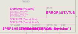
Figure 6: While you are setting up drawing templates, the notes that are linked to external properties will display placeholder values.
I frequently use a document management system—WPDM—with its options set to update the custom properties Revision and Status during check-in. The document management system has its own methods for assigning revisions, so I like to see both revision properties displayed in my title blocks. This makes it easier to spot tangles with the vault, which is what the document management’s server is called.
How does one create a custom property? With the part or assembly open, one method in SolidWorks is to click the menu sequence File>Properties to launch the Summary Information dialog. That’s how Figure 4 got made.
This dialog has a Summary tab and a Custom tab; it will have a Configuration Specific tab if the part or assembly has more than one configuration.
The Custom tab and the Configuration Specific tab are nearly identical in function. The Summary tab is not really part of this discussion.
If the part or assembly does have configurations, then the Custom tab will list the properties that are common to all configurations. The Configuration Specific tab will list the properties that are unique to each configuration. If a property with the same name shows up on both the Custom tab and the Configuration Specific tab, then the Configuration Specific tab will have the property value that will be displayed on the drawing. Configuration-specific properties overwrite the defaults found on the Custom tab.
To create a new custom property, make sure that either the Custom tab or the Configuration Specific tab is active. Then select a blank row in the table and start typing the name of the property in the Property Name column. I generally leave the type set as Text, which is the most forgiving. If you need to restrict the values to numbers or dates only, then Number or Date might be a better type for your property.
In the Value/Text Expression column, enter a value. For example, you might enter Number for the Property Name, Text for the Type, and CT-0100 for the value. Be sure to click on OK to save the changes you’ve made to the custom properties list.
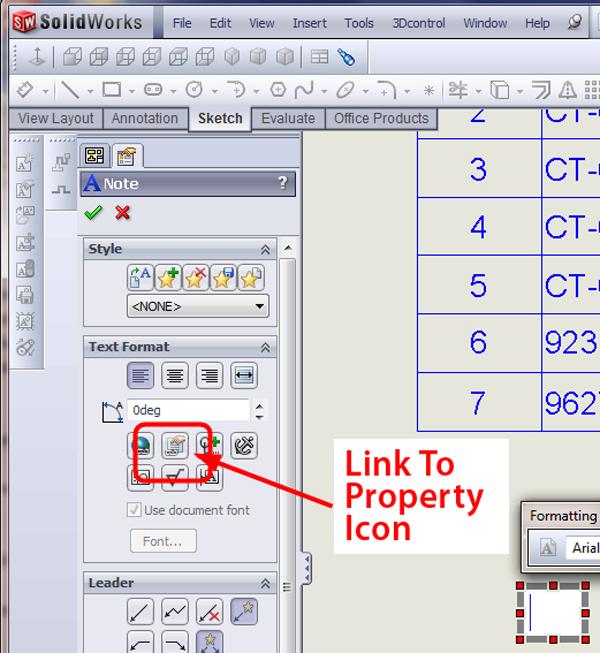
To use a custom property in a title block on a drawing or drawing template, open the drawing or drawing template, use the menu sequence Insert> Annotations>Note, and click where you want the property to be displayed on the template. Then click on the Link to Property icon (see Figure 5a). The Link to Property dialog will appear. If we are setting up to display a property that is stored in the part or assembly, then we would click on the radio button to select Model in view specified in sheet properties (see Figure 5b). If the desired property should be found in the drawing instead of in the part or assembly, then we would use the radio button for Current document.
The list of available properties then can be displayed by clicking on the down arrow at the right of the data entry field. For example, in Figure 5b, the Project property is highlighted in the list of available properties. Once the desired property has been selected, click on OK. When you are setting up drawing templates, this process requires a little bit of faith. The template does not have any specific part or assembly associated with it. It will display the links to the values instead of the values. You won’t see a proper display of the values until a new drawing is created using this template for a part or assembly that has the right custom properties. You can opt to display any link errors with the menu sequence View>Annotation Link Errors. The result is shown in Figure 6. There is an error to the link for Status because the property Status does not yet exist in this drawing.
Now let’s get back to the topic of data entry for all of these custom properties. If you have spent much time using the File>Properties>Summary Information dialog, you’ll probably agree with me that it is not the easiest data entry form in the world to use.
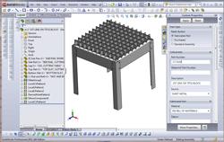
Figure 7b: The form created in Figure 7a flies out to the right of the graphics window.
The Property Tab Builder—Figure 7a—is a piece of software that ships with SolidWorks. This tool allows a CAD administrator to design a data entry form.
Once the form’s design and layout are complete, then it can be published and used during a routine modeling session to create automatically all of the custom properties needed to match the drawing template, which also is created by the CAD administrator. Publishing consists of setting the SolidWorks workstation’s File Location options for Custom Properties to point to the folder where the Custom Properties Form was saved by the CAD administrator. The CAD operator will find a suite of three forms—one for parts, one for assemblies, and one for drawings. They all need to be in the same folder.
The resulting form created in Figure 7a appears ready to use in Figure 7b. The data displayed in this form depends upon which component in the Feature Manager has been selected. This makes it easy to traverse the assembly and catch up on the data entry. Additionally, the data entry process for this form is very Windows-like. The users of the form definitely will prefer it over the Summary Information dialog, even though both methods of data entry accomplish the same thing.
Next month we’ll take a closer look at setting up templates for drawings and BOMs. A good set of templates will speed the modeling process and will also result in better consistency between projects over time.
Another great use for custom properties is the modeling of part markings. Stay tuned.
Gerald would love to have you send him your comments and questions. You are not alone, and the problems you face often are shared by others. Share the grief, and perhaps we will all share in the joy of finding answers. Please send your questions and comments to dand@thefabricator.com.


The Fabricator is North America's leading magazine for the metal forming and fabricating industry. The magazine delivers the news, technical articles, and case histories that enable fabricators to do their jobs more efficiently. The Fabricator has served the industry since 1970.
start your free subscription
Easily access valuable industry resources now with full access to the digital edition of The Fabricator.

Easily access valuable industry resources now with full access to the digital edition of The Welder.

Easily access valuable industry resources now with full access to the digital edition of The Tube and Pipe Journal.

Easily access valuable industry resources now with full access to the digital edition of The Fabricator en Español.
Patrick Brunken, VP of Addison Machine Engineering, joins The Fabricator Podcast to talk about the tube and pipe...


