


Contributing Writer

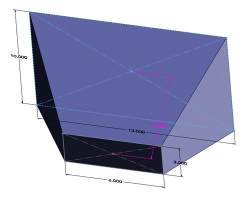
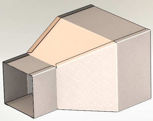
Figure 1: This is the transition piece of ducting that we are tasked with fabricating.
I worked in a job shop for a couple of decades. I frequently had my customers’ engineers assure me that suggestions to improve their designs were always welcome. It was occasionally disconcerting to make suggestions without seeing subsequent changes showing up in the design.
The reasons for not implementing good ideas are as numerous as the situations in which suggestions are “ignored.” The most common reason might be the cost of implementation. If the cost is greater than the perceived benefit, then the suggestion is likely to get shelved.
Before we go any further, let’s start with the usual disclaimer that we’re examining some modeling functionality that is unique to the software I’m using. Keep in mind that challenges to getting good ideas implemented are not at all unique to a specific brand of software.
Let’s consider the design process for a sheet metal part as shown in Figure 1. The design intent for this transition piece is to make it easy to adjust. This could be accomplished by editing the distances between the profile sketches and the shape of those two profile sketches. The designer has proposed a shape for the prototype by selecting some initial values for the dimensions, but those values most likely will need to be changed after evaluating the part in actual operation.
Our designer has modeled the part’s sheet metal features using an inside bend radius that is equal to the material thickness—in this case, 18-gauge (0.048-in.) cold-roll steel.
The manufacturer would prefer a slightly different inside bend radius, more like 0.030 in. instead of 0.048 in. What are the costs involved in changing the bend radius? From the fabricator’s point of view, the flat-pattern calculations are the main bump in the road. If the 3-D CAD model was correct, then the unfolding process is automatic—essentially labor-free. Because the 3-D model is not correct in the fabricator’s opinion, then extra labor is expended each time the flat pattern is calculated. Presumably, the fabricator’s extra cost will be reflected in the price charged for the part. This extra expense probably will show up as a one-time CNC programming fee—one-time meaning the fee is charged once each time the revision changes.
From the designer’s point of view, the cost of ignoring the fabricator’s suggestion is hard to quantify unless the fabricator states how much it costs to recalculate the flat layouts manually using the ideal bend radius. It is much easier for the designer to identify the in-house costs of implementing the suggested change. Let’s discover what the designer already knows so we might understand how easy it is to change a bend radius.
The designer decided to have this transition duct fabricated as four sheet metal parts that are spot welded together. These four wall pieces will be modeled parametrically so they always match the desired shape.
Figure 2a shows the designer’s starting point. This is a model of what the inside of the duct needs to be. The modeling of the sheet metal parts will come later. The designer created two planes that are 6 in. apart. A 10- by 12-in. rectangle was sketched on one plane and a 6- by 3-in. rectangle was sketched on the second plane. A lofted extrude was created using those two sketches.
Those same sketches were used to create boss-extrudes to complete the shape of the desired internal volume as shown in Figure 2b. Simple edits to those dimensions will be all that is needed to change the duct’s internal shape.

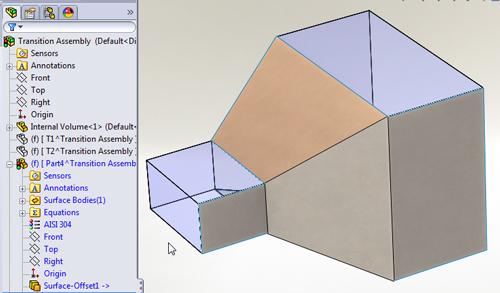
Figure 3a: Three connected surfaces are offset in preparation for creating a sheet metal wall.
This internal volume part was then inserted into an assembly. The four sheet metal parts were modeled in the context of that assembly using the internal volume part as reference geometry. If the internal volume model is changed, we expect the sheet metal parts to automatically update accordingly.
To model the separate sheet metal parts the designer used a two-step technique for each part—offsetting the desired surfaces and then converting that surface offset to sheet metal. In Figure 3a we see that the surface offset distance was set to 0 and that three connected faces were selected. In Figure 3b we see that one of the faces was selected as the fixed entity, and two edges were selected to identify the bends. The material thickness and inside bend radius were set to 0.048 in.
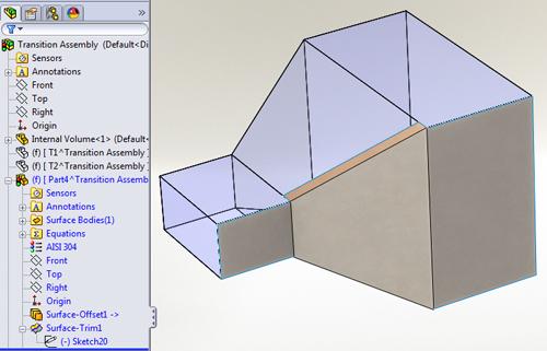
The side walls have the additional complexity of flanges for spot welding. To avoid having to specify a bend angle for the sloped transition flange—we want the angle to be driven by the internal volume—five surfaces were offset (see Figure 4a). Then the Surface-Trim tool was used to cut the surfaces that will become flanges back to about 0.75 in. (see Figure 4b).
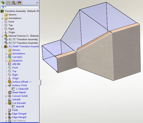
The Convert-To-Sheetmetal tool was then used to create a sheet metal part from the offset surfaces (see Figure 4c). The convergence of bends creates the need for bend reliefs to trim away material, so a Cut-Extrude was used to remove unwanted material.
Once the four wall parts are created, we arrive back at the assembly shown in Figure 1. We can test the design intent of the model by editing the internal volume part. Figure 5 demonstrates that changing the shape of the internal volume will result in updated sheet metal parts.
Now we can answer part of the original question: What is involved with changing the inside bend radius of the sheet metal parts? The inside bend radius can be changed by editing the Sheet-Metal feature—from 0.048 in. to 0.030 in. as shown in Figure 6. This operation is repeated for each of the four sheet metal parts. That simple editing does not take very long by itself.
However, editing dimensions in the 3D-CAD model is just the first step. We need to update the fabrication drawings and get those updated files into the hands of our purchasing and production departments.
It isn’t the dimensions on those drawings that are hard to update; you only have to open up the 2-D drawings and let them rebuild to match the 3-D CAD models. The tedious work comes in the form of updating the revision letters and revision history in the title block.
Before we make a change to our 3-D CAD database, we really should start with an engineering change order (ECO). The ECO documents the reason for the change, as well as the disposition of the prior-revision inventory. An elaborate ECO system might include sign-offs from various departments, routing, and instructions about field reworks.
If we’re working with a document management system, sometimes referred to as a vault, then another level of coordination must be implemented. I’ve worked both with and without automated document management. I prefer to work with it. It helps to coordinate the assignment of revision levels, provides for excellent data backup, and helps to prevent accidental design changes.

Figure 3b: The surface offset is converted to sheet metal. This is where the thickness and bend radius are specified for the first time.
SolidWorks® ships with Workgroup Product Data Management (WPDM). It is a minimalist approach that works well for small teams of collaborators. For larger teams and bigger projects, Enterprise PDM is sold as an add-in. PDM software automatically issues new revision letters for the documents each time they are checked into the vault. In conjunction with the ECO system, PDM might be the ultimate method of informing purchasing and production as to what the active revision of the design is.
Rather than listen to the designer’s litany of woes about ECOs and PDMs, the fabrication shop might decide that the path of least resistance is to use a technique as described in the October column: Just import the sheet metal parts as dumb solids and insert bends with the desired bend radius. Some hazards may arise with this approach. For example, the end of a flange might be defined as tangent to a bend radius; if the radius changes, the end of the flange will move. Is that OK? That’s hard to answer unless you are the designer.
After the fabrication shop edits the model—either by FeatureWorks® to re-create the model without external links, by inserting bends into an imported solid, or even by editing a top-level assembly similar to the one used by the original designer—the designer and the fabrication shop need to address the problem of getting that updated model and related drawings into the vault. The designer might be very reluctant to replace the original models with the fabrication shop’s updated models because of the possible existence of external references that might be broken. Migrating the updated models into the vault can be done, but it must be done carefully and diligently to maintain the integrity of the parametric links.
So what is the helpful fabricator to do? Give up on making suggestions to improve the design? Not at all! The best course of action is to communicate.
Be aware of the full scope of responsibilities that each member of the team has. Proceed in a way that is coordinated to avoid redundant effort.
Gerald would love to have you send him your comments and questions. You are not alone, and the problems you face often are shared by others. Share the grief, and perhaps we will all share in the joy of finding answers. Please send your questions and comments to dand@thefabricator.com.

Figure 6: To change the bend radius, the Sheet-Metal feature is edited in each of the four wall parts.


The Fabricator is North America's leading magazine for the metal forming and fabricating industry. The magazine delivers the news, technical articles, and case histories that enable fabricators to do their jobs more efficiently. The Fabricator has served the industry since 1970.
start your free subscription
Easily access valuable industry resources now with full access to the digital edition of The Fabricator.

Easily access valuable industry resources now with full access to the digital edition of The Welder.

Easily access valuable industry resources now with full access to the digital edition of The Tube and Pipe Journal.

Easily access valuable industry resources now with full access to the digital edition of The Fabricator en Español.
Cameron Adams of Laser Precision, a contract metal fabricator in the Chicago area, joins the podcast to talk...


