


Contributing Writer

Figure 1: This example of an ornament with a hanging loop is the first in our product line.
In the spirit of the holidays, we’re going to discuss library features. Our goal is to model a product line of laser-cut ornaments (see Figure 1). Each ornament is unique, but all have a common feature—a hanger loop.
Before we get started, please note that we’re examining some modeling functionality that is unique to the software I’m using. Most major brands of 3-D CAD software have some form of library function to minimize the starts-from-scratch in modeling.
Now let’s get back to the modeling. We want to create the hanger loop once (see Figure 2) and reuse it in each of the ornament models. That should help speed the modeling process. If we have several CAD jockeys working on the project, it will help standardize the hanger loop design.
A few documents are involved in this process:
The ornament parts could be created without the library feature’s documents, but it would involve fully re-creating the sketch and the boss for the hanger in each ornament. We are more interested in a drag-and-drop approach—what I think of as the easy-as-pie way—because we’re professionals.
The library feature’s file will have an extension of SLDLFP and will be stored in a folder of your choosing. If that folder is in a shared location, then other engineers can access the feature easily. All they need to do is include that folder in their Design Library in their Task Pane.
The Development Part that is used to create the library feature won’t be revised very often—perhaps only once, but more likely a few times while the drag-and-drop functionality is refined. Once that initial testing is completed and the SLDLFP file resides in the Design Library folder, this Development Part will be forgotten and can be deleted.
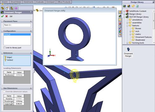
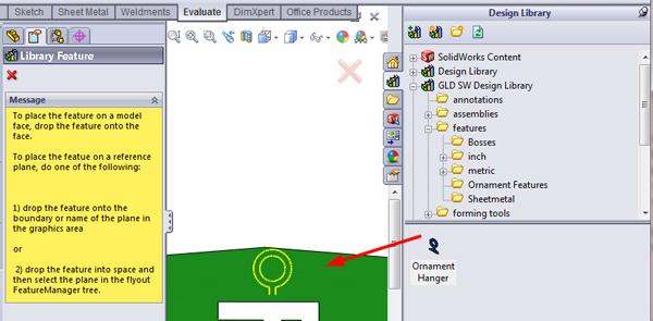
It is useful to anticipate how the drag-and-drop process will be experienced when you ultimately use the library feature. Figure 3 is a screen shot of me dragging a loop onto an ornament. After the mouse is released to drop the library feature onto the part, the system prompts me to select the needed target features and perhaps to enter values for the needed positioning dimensions.
You’ll note that the preview window in Figure 3 has one edge highlighted. You’ll also note in the Property Manager to the left that there is a References box with questions about Edge2 and Vertex2. The preview window is showing me which question the system currently wants me to answer. In this case, it wants me to select an edge on my target part.
As we progress through the refinement of our library feature’s drag-and-drop functionality, you’ll notice that the library feature wants to snap into position. That is the result of cleverly creating what are termed references. These are merely external sketch relations that are set up in the feature’s sketch in the Development Part.

Figure 2: A close-up view of the hanger loop library feature is shown.
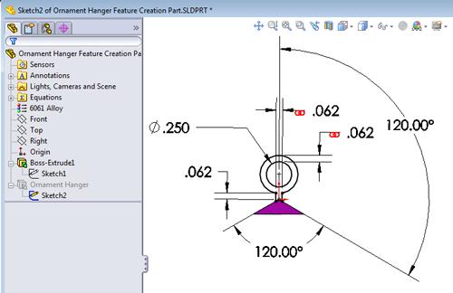
In Figure 4 you can see a sketch in progress. This sketch has an angle dimension referencing Boss-Extrude1—a feature that is outside the sketch’s context. This is an external reference.
When you are actually using a library feature, for each external reference in the library feature‘s original sketch, you will be prompted to select a feature on the target part. The type of target feature to select will depend on the corresponding type of sketch relationship. As each selection is completed, the library feature will move further into position.
It is good practice to give positioning references friendly names so that it is easier to complete the drag and drop without thinking too hard. If you like, the friendly names can be set up while editing the feature’s sketch in the Development Part. In that case, they will migrate into the library feature’s SLDLFP file. If the library feature has been released for use, you can revise the friendly names anytime by editing the SLDLFP file.
Once the library feature is in our target part—in this case once the hanger loop is on the ornament—we could dissolve the feature and lose all connection to the design library. That might be desirable if a CAD operator has no interest in standardization of the feature. However, we have no desire to dissolve our library features at this time.
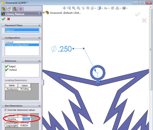
A slightly less drastic method of creating a nonstandard standard feature is to override the default dimensions in the library feature’s entry in the Feature Manager. Figure 5 shows that the original 0.250-in.-diameter hole is being resized to 0.500 in. diameter. These overrides apply only to the target part, the ornament in our example. The changes do not propagate back to the master library feature.
We can control which dimensions can be overridden by making the dimension internal. Editing the library feature’s SLDLFP file accomplishes that, as we will see shortly.
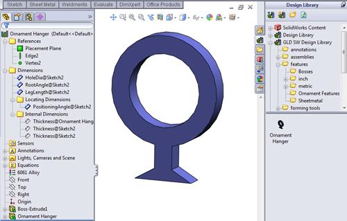
Figure 6 shows the result of me using my right mouse button to open the Ornament Hanger library feature from my Design Library. In its Feature Manager shown to the left, you will find several feature folders. The Dimensions folder has all of the dimensions created in the Development Part that referenced external features. Any dimension can be renamed to result in a better prompt for the user during drag and drop.
All of the dimensions in the Dimensions folder can be overridden by the end user. Drag the dimension from the Dimensions folder into the Internal Dimensions folder to prevent it from being overridden. If the dimension is used only for locating the feature, drag the dimension into the Locating Dimensions folder. That makes editing the position of the library feature easier.
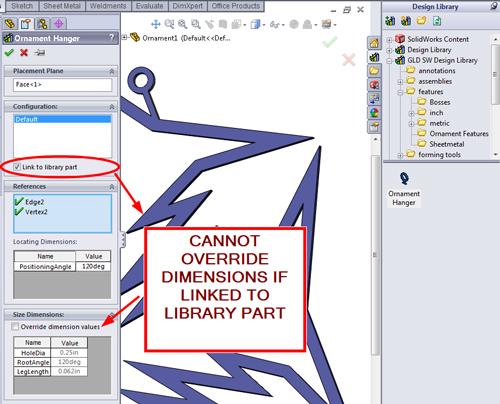
The problem with overriding a library feature’s dimension is that it creates a nonstandard feature. To avoid this problem, all overrides are disabled if the Link to Library Part option is selected when inserting a library feature into a part (see Figure 7). Any changes made to the library feature’s SLDLPF will propagate to any part that is linked to the library part. Of course, the target part must be opened and rebuilt before the linked change will be apparent.
To review, back in Figure 4 we created a Development Part. The Development Part has a dummy base feature that we don’t really care about. It also has an extruded feature that is our hanger loop. We’ve renamed that feature, Ornament Hanger, with a friendly name out of good habit.

Figure 10: The second part in our line of ornaments sports the same hanger as that shown in Figure 1.
To get ready to create the library feature SLDLPF file, we pinned the Task Pane to stay open, selected the Design Library tab, and created a folder. The third and final step in creating the SLDLPF file is to drag the feature—now named Ornament Hanger—into the lower half of the Task Pane. In response to that drag and drop, the system will present the Add to Library Property Manager. You must enter a file name, which will be the name of the SLDLPF file. You should enter a description to remind your future self what this thing is. Click in the green check mark to dismiss the Property manager. Figure 8a shows our new Ornament Hanger library feature residing in its folder.
We now can close the Development Part and might never use it again.
Next we open the SLDLPF file from the Design Library and expand its Feature folders. Figure 8b shows my final rearrangement of the references in their folders. The only dimensions in the Dimension folder are those that I’m willing to let anyone customize. Putting the angle dimension in the Locating Dimensions folder makes it easier to position the feature on the part. I also renamed the items in the References folder to be friendlier.
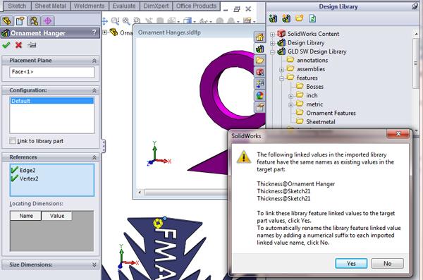
In Figure 9a we have a target ornament part opened and have clicked on the library feature in preparation for dragging it onto the target part. Note that the description we entered appears in the popup window in the Task Pane when we pause the mouse over the library feature in the Design Library. As we drag the ornament hanger into the Graphics Window, the system prompts us to select a target feature (see Figure 9b).
In Figure 9c we have dragged and dropped the library feature—Ornament Hanger—onto the target part and selected the needed face, edge, and vertex. A question pops up about thickness. I want the new feature to link to the target part’s thickness, so “Yes” is the correct answer.
The hanger feature came in at a funny angle with the edge I selected, so I had to edit the positioning angle, as shown in Figure 9d.
After clicking on the green check mark to dismiss the Property Manager, we have another ornament completed for our product line (see Figure 10). It is remarkable how quickly these hanger loops can be added now that we have the library feature set up.
Gerald would love to have you send him your comments and questions. You are not alone, and the problems you face often are shared by others. Share the grief, and perhaps we will all share in the joy of finding answers. Please send your questions and comments to dand@thefabricator.com.


The Fabricator is North America's leading magazine for the metal forming and fabricating industry. The magazine delivers the news, technical articles, and case histories that enable fabricators to do their jobs more efficiently. The Fabricator has served the industry since 1970.
start your free subscription
Easily access valuable industry resources now with full access to the digital edition of The Fabricator.

Easily access valuable industry resources now with full access to the digital edition of The Welder.

Easily access valuable industry resources now with full access to the digital edition of The Tube and Pipe Journal.

Easily access valuable industry resources now with full access to the digital edition of The Fabricator en Español.
Cameron Adams of Laser Precision, a contract metal fabricator in the Chicago area, joins the podcast to talk...


