Contributing Writer
- FMA
- The Fabricator
- FABTECH
- Canadian Metalworking
Categories
- Additive Manufacturing
- Aluminum Welding
- Arc Welding
- Assembly and Joining
- Automation and Robotics
- Bending and Forming
- Consumables
- Cutting and Weld Prep
- Electric Vehicles
- En Español
- Finishing
- Hydroforming
- Laser Cutting
- Laser Welding
- Machining
- Manufacturing Software
- Materials Handling
- Metals/Materials
- Oxyfuel Cutting
- Plasma Cutting
- Power Tools
- Punching and Other Holemaking
- Roll Forming
- Safety
- Sawing
- Shearing
- Shop Management
- Testing and Measuring
- Tube and Pipe Fabrication
- Tube and Pipe Production
- Waterjet Cutting
Industry Directory
Webcasts
Podcasts
FAB 40
Advertise
Subscribe
Account Login
Search
3-D CAD modeling case study: A great industrial design can be burdened with inadequate planning
Design for manufacturability concepts, document control, and clarity on method of assembly help industrial designs become a reality
- By Gerald Davis
- April 12, 2018
- Article
- Shop Management
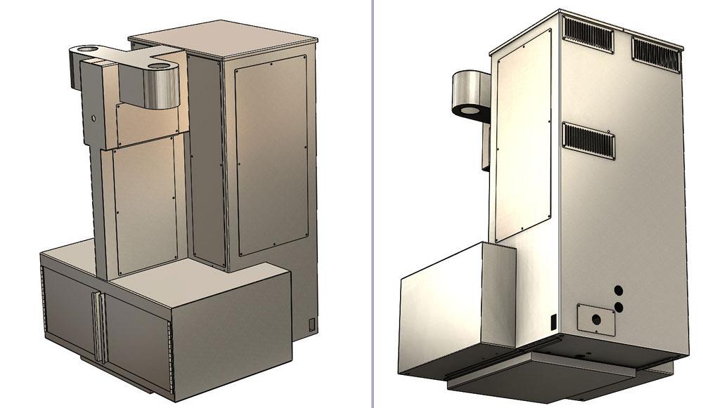
Figure 1a
The original industrial design was converted in 3-D CAD into parts suitable for various trades. This is the sheet metal portion of the design. Note that machined and molded parts are not included in the information provided to the sheet metal fabricator.
Disclaimer: This case study of a coffemaker’s sheet metal cabinet features a pair of inventors doing their best without the benefit of experience in manufacturing.
The previous edition of this column (“An industrial design makes the transition to something that’s made,” Precision Matters, The FABRICATOR®, March 2018, p. 38) discussed some of the challenges posed by moving from the ideal to the practical.
In the story so far, design for manufacturability (DFM) was to be delegated to the winning bidders. The STEP file modeled the desired shape. That shape was based largely on the industrial design (see Figure 1a). Work went into the CAD model to indicate which parts would be machined rather than fabricated from sheet metal. As shown in Figure 1b, the fabricator would be able to create an exploded view to show detail regarding covers and frame. Sadly, the STEP file cannot convey the exploded view that happens in the native CAD. Happily, in the STEP file, the models were grouped into subassemblies to indicate “weldment,” but it required some study to understand the nuances.
The request for quote that accompanied this STEP file explained that the job shop was to apply its best judgement in deciding how the welding and grinding of the sheet metal would be completed. The immediate need was for as many as three cabinets, but the absolute must-have was at least one completed cabinet.
“Success” during the early stages of this project could be defined in many ways. Industrial design efforts led to an attractive cabinet. The initial DFM efforts identified methods of manufacture—sheet metal fabrication, machining, or injection molding—which would make it easier for the fabricators of the cabinets to make shop drawings.
The design had some shortcomings, though. The absence of models for the internal components meant that their mounting was “to be figured out at assembly time.” So the design reserved approximate space for the internal components, with the intention of matching drilling holes as needed for mounting relays and routing tubing. Of course, this “quick-CAD” approach caused tedious work and extensive labor for the final assemblers. Even though the machine worked at the trade show, under the unit’s pretty painted covers the interior components were held together with zip ties and duct tape.
The fabricator was responsible for DFM; creating production drawings; and making decisions regarding fasteners, finish, and part numbers. Material strength and thickness were assumed to be enough based on the industrial design. The results of those assumptions, however, were weak parts that should have been strong, and incredibly strong parts that served minimal purpose.
Document and revision control was accomplished with phone calls and marked-up prints. The consequences included frustration and hot tempers when accept/reject decisions were based on recollection rather than printed fact.
At the trade show, where the coffeemaker debuted, the folks showcasing the coffeemaker answered questions about commercial availability with vague assurances that production would happen. But before that could happen, a few changes needed to be made first. Sheet metal screws that stripped out after only one use needed to be addressed. Ugly welds were visible because of limited access for grinding. A leg fell off the machine when a weld nut failed. Some of the electronic components were not screwed down completely. Service access was inadequate. Razor-sharp edges turned service and assembly into a hazardous activity.
In retrospect, the shop drawings represented intellectual property that needed to be defined and controlled as part of the overall machine design. Over time it became necessary to recreate those fabrication drawings as part of controlling the business. Sadly, the transfer of drawings from the fabricator back to the owner was not discussed up front.
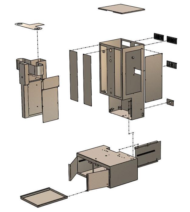
Figure 1b
The initial design for manufacturing included subweldments and cover plates. The exploded view was visible in native 3-D CAD, but was lost in the STEP file that was sent to fabrication. All the STEP file showed was subassembly, not method of assembly or method of welding and grinding. Even the grain direction was delegated to the fabricator.
The history of frustration over revisions and design, coupled with schedule pressures and inadequate planning, made the conversations about who owned the drawings unnecessarily contentious. Our heroes ended up reverse-engineering the final design for ideas that they had originally created. That was redundant effort taken to a wasteful extreme.
The problems with this first cabinet caused it to be a one-off. That’s sad, because the industrial design was pretty good. The initial DFM work also was done well. The problem existed in the execution details: the mounting and routing, the revision control, the grain direction, the size of the screw, and all of the verbal communicating in the midst of trying to figure out things on the fly with an 18-V drill. All of it limited the design to a one-time build.
The Next Step
The trade show was a success and generated demand for the machine. The next step was ramping up for mass production—or at least a build of 10. Our heroes now had some experience in manufacturing. What would they do to get the next-generation machine ready for market?
Next month you will learn how I was recruited to help with the effort. My approach to all projects is to create a detailed virtual prototype in CAD. That CAD model-to-be will be fundamental to the future of coffee as we know it.
Please send your questions and comments for Gerald Davis to dand@thefabricator.com.
About the Author
subscribe now

The Fabricator is North America's leading magazine for the metal forming and fabricating industry. The magazine delivers the news, technical articles, and case histories that enable fabricators to do their jobs more efficiently. The Fabricator has served the industry since 1970.
start your free subscription- Stay connected from anywhere

Easily access valuable industry resources now with full access to the digital edition of The Fabricator.

Easily access valuable industry resources now with full access to the digital edition of The Welder.

Easily access valuable industry resources now with full access to the digital edition of The Tube and Pipe Journal.
- Podcasting
- Podcast:
- The Fabricator Podcast
- Published:
- 04/30/2024
- Running Time:
- 53:00
Seth Feldman of Iowa-based Wertzbaugher Services joins The Fabricator Podcast to offer his take as a Gen Zer...
- Industry Events
Pipe and Tube Conference
- May 21 - 22, 2024
- Omaha, NE
World-Class Roll Forming Workshop
- June 5 - 6, 2024
- Louisville, KY
Advanced Laser Application Workshop
- June 25 - 27, 2024
- Novi, MI
Precision Press Brake Certificate Course
- July 31 - August 1, 2024
- Elgin,

