


Contributing Writer

Figure 8: The Sheet Metal Costing tool makes it easy to see the impact of material and feature count on cost.
Editor's note: Resources that accompany this article include a video that is an extension of this topic; a zip file that has the equation-driven model in SW12 format along with the prtprp form from Property Tab Builder; and a discussion forum.
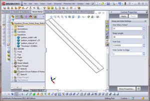
Figure 1a is a screen shot of a 48-in. part with 47 holes equally spaced and centered along its length. In Figure 1b, the data in the Custom Properties form has been changed to specify a 6-in. part with two holes. Both figures use the same CAD model; no edits were made to sketches. Just type, click on Apply, and then click on Rebuild to change the model.
This Custom Properties form includes controls for the size of the holes and for the holes’ proximity to the ends of the strap. To create this form-driven model, we need to
Figure 2 shows the starting sketch for this project. It is just a rectangle centered on the origin for convenience. It could be a rectangle located anywhere. The starting dimensions are arbitrary. We just need to create the dimensions so they will be available for connection to the equations.
We also will need some custom properties. They will connect the data entry form to the sketched model. Figure 3 shows the setup of a custom property named Strap_Length. It is set to have a value of 6.000 just as a starting point.
Connecting dimensions or custom properties to equations is just a matter of perfect typing. The equation must have the exact name of the dimension to control. You can type in the entire equation if you are really careful. To make the job of perfect typing easier, click on a dimension to automatically copy its name into the equation editor, thus eliminating the chance for errors.
To make that work, you need to have things open as shown in Figure 4a. We have opened the Equation Manager (Tools>Equations). We also clicked on the sketch to get it to show its dimensions in the Graphics Window. The first step is to position the cursor in the Equation Manager and place it in the location where you want the dimension to go. Figure 4b shows the result of clicking on the 6-in. dimension to copy its name—D2@Sketch1—into the Equation Manager.
The cursor automatically moved to the Value/Equation column. The dimension will take on the value that we create here. To set that value, we need to type in an equation.
You’ll notice a drop-down menu appeared that allows me to click to select Functions, File Properties, or to enter a constant. If we always wanted this dimension to be 6.000, we could just type =6 and be done.
What we want to do instead is select the File Properties as the source for this element of our equation. From that list of File Properties, we’ll select Strap_Length (see Figure 4c). It is always a good idea to add comments to your equations. I added a comment of “Overall length of strap” to remind me of what my Custom Property Strap_Length is intended for.
We repeat the setup of file properties and linking them into our equations. Figure 5 shows the result. We created a global variable named pattern_width, which is at the top of the table in Figure 5. This is the center-to-center maximum size of the hole pattern and is based on the distances from edges to hole and the distance from edge to edge.
To center the pattern on the blank, we just divide the pattern width in half. That’s what the Global Variable pattern_midplane calculates.
To determine the distance between holes, divide the overall width of the pattern by the number of intervals. The number of intervals is one less than the number of holes.
At the bottom of the Equation Manager’s table we use a combination of File Properties and Global Variables to control dimensions in the sketches. I left most of the dimension and sketch names “as created.” You’ll note they are rather mysterious. The one at the bottom, StrapLength@Sketch1, shows the benefit of giving your dimensions meaningful names before linking them to an equation. I strongly recommend that you use good names for dimensions and features, especially when you use them in equations.
As you develop the equations, test them at each step and fix any typographical errors. Pay attention to the Evaluates to column in the Equation Manager’s table. Look for unexpected results!
We could have set up the Custom Properties form with the Property Tab Builder first, but we didn’t. Figure 6 shows the Property Tab Builder. This is launched with Start>All Programs>SolidWorks>SolidWorks Tools> Property Tab Builder. Controls you can use appear on the left. The form you are designing is in the middle. Set the names and spelling using the right section of the screen: Just drag a control onto the form and type to make it yours.
In Figure 6 we’ve selected the number control at the top of the form. This is where we want a person to enter the desired number of holes. To let the person know this, we edited the caption to ask, “How many holes?” To make sure this form matches our equations, we entered the name for this control so it exactly matches the Custom Property name we used in our equations. We also entered a default starting value to help out the person responsible for determining the hole count.
It is possible for human intervention to result in values that will cause the model to fail to rebuild. For instance, asking for fewer than one hole would be bad. Asking for more holes than strap also would be bad. We could add conditional logic to our equations to prevent bad data entry from killing the model. That is beyond the scope of this demo, however.
To complete the form in Figure 6 we repeated the setting of captions, names, and default values for the other controls on the form. When it is finished, we give it a good name—HoleStrap.prtprp—and save it in a location we can remember. We now leave the Property Tab Builder and return to SolidWorks.
Now that we have a form, we need to tell the workstation to use it. Clicking on the menu sequence Tools>Options>SystemOptions>File Loca- tions>Custom Property Files leads you to Figure 7. I browsed to the location where I saved the HoleStrap.prtprp form and then clicked OK. You can have only one of each kind of form file in the folder, by the way. That means only one set of prtprp, drwprp, and asmprp files per folder.
The workstation options now are set to use the Custom Property forms found in the right folder. The forms set custom properties that have names that are properly spelled in our equations. The equations are connected to dimensions in sketches that control the model. We now demonstrate the functionality shown in Figures 1a and 1b.
For our next trick, we’ll use the Sheet Metal Costing tool to observe the consequences of changing the size and number of holes as they relate to cost. Figure 8 is a preview of the costing tool. This is available with the professional and premium license suites. If you have just a standard license, you don’t have costing capabilities.
The costing tool tries to recognize the part as machined or sheet metal. If it is sheet metal, it counts things like bends and forming tools. Those are not included in estimates for machined parts. The costing tool recognizes the results of your modeling techniques, not how you did it. It gives you a summary of what it recognized, shown on the left side of Figure 8. You can override the prices shown or adjust the templates behind those prices.
For those in the estimating trade, this tool is bare bones. It provides a good indicator of impact on cost for material and feature changes. It does not try to deal with efficiencies of scale; parts built in larger batches have lower unit costs than one-off parts. Beyond that, however, a CAD operator can use the controls in the database to turn this into a pretty good ballpark estimator.
If you’d like to learn more about setting up the costing tool, stop by next month. We’ll poke around under the hood in a bit more detail.
Gerald would love to have you send him your comments and questions. You are not alone, and the problems you face often are shared by others. Share the grief, and perhaps we will all share in the joy of finding answers. Please send your questions and comments to dand@thefabricator.com.


The Fabricator is North America's leading magazine for the metal forming and fabricating industry. The magazine delivers the news, technical articles, and case histories that enable fabricators to do their jobs more efficiently. The Fabricator has served the industry since 1970.
start your free subscription
Easily access valuable industry resources now with full access to the digital edition of The Fabricator.

Easily access valuable industry resources now with full access to the digital edition of The Welder.

Easily access valuable industry resources now with full access to the digital edition of The Tube and Pipe Journal.

Easily access valuable industry resources now with full access to the digital edition of The Fabricator en Español.
Patrick Brunken, VP of Addison Machine Engineering, joins The Fabricator Podcast to talk about the tube and pipe...


